eBoost Battery - Inverter Integration Guide
Important notice
This Quick Guide does not exempt the installer or User from reading each product manual. Failure to do so may risk damaging both Fortress Power equipment and other manufacturers and void warranty.
Abbreviations
Connection diagrams
Connection Overview
One eBoost Battery and Envy Inverter Electrical Connection Overview
When operating with one eWay, keep the terminator plug placed in its original position.
Plug one side of the BAT-PCS cable into the RJ45 ports of the Communication board and the other side into the inverter BAT COM port. RSD features include complete system shut off by disconnecting the batteries voltage output, Disabling PV Voltage, and Load Output per NEC 2023 Code. To achieve this, Follow the connections in the above image.
Two or more eBoost Batteries and Envy Inverter Electrical Connection Overview
Remove the terminator from the first eWay and
place battery to battery communication.
Make sure that the secondary eWay keeps the terminator
connected in its original port. Repeat this process with batteries connected in
parallel by connecting the Battery -Battery RJ45 Cables in daisy chain sequence
starting with the first battery to the last. Place the Resistive RJ45 plug into
the terminator Port of the last secondary battery following chronological
sequence starting with the Primary Battery. Lastly, plug the ‘RACK1-RACK2
ENABLE “cable from the primary battery to the secondary.
For More
details of parameter settings, please refer to the Fortress Power Envy
12kW/10kW/8kW Manual.
Fortress Power Envy Integration
Closed loop and pinout definitions
COMMISSIONING
For Commissioning batteries where multiple eWay are in parallel, please go to the “Commissioning in Parallel” section.
1. Turn the battery breaker inside the inverter. See below.
2. Turn the RSD Switch to the ON position.
3. Press the Power button. Make sure to select the correct inverter protocol by holding the power button for 5 seconds after initiating the battery.
4. Verify Voltage by applying a voltmeter at the eWay internal busbar. Voltage should be around 49-52.5V
5. Inverter Communication Protocol
To select the inverter protocol to achieve closed loop communication, you must press and hold the power button for 5 seconds, then release it. Immediately the LED 6&7 will start flashing following the current inverter protocol status. In this stage, press the button once until you select the correct protocol as shown in the images below.
Fortress Power Envy
Before setting the parameters, make sure the
system is in Standby. Make sure to press SET for each setup.
Confirm the battery is doing Closed Loop Communications with the Primary
inverter under the Battery of the Data Section.
Battery Set Up
Battery
Capacity: 314ah per battery
Discharge Current: 250A per Battery
Self-Consumption Mode
Back up
Off-grid
Sol-Ark
Share Sol-Ark Monitoring w/Fortress
Set up Wi-Fi with Sol-Ark Inverter using Sol-Ark’s My Sol-Ark App and have your site name and Wi-Fi dongle serial number handy to register the system online with Sol-Ark. After registering, use a laptop to log into MySolArk via a web browser at http://mysolark.com
Note: For certain circumstances, temporarily use the batteries in open-loop communication mode, please follow the following link for open-loop settings:
Programming:
1. To program the inverter using the Sol-Ark inverter screen, go to battery
setup menu:
2. Program the 'Batt' tab first. Enter the settings as shown below and tap on 'OK' at the bottom of the menu afterwards:
Closed Loop Settings
Confirm closed loop communication was established by going to the Home screen and selecting Li-BATT INFO.
Note:
a) If closed loop communication is set up correctly, enabling 'BMS Lithium Batt 00' will adjust some values automatically. In this tab, those would be 'Batt Capacity' and 'Tempco'.
b) If the total charge/discharge current capacity of the batteries exceeds the inverter's capabilities, use the maximum current settings of the inverter.
For example, if you have four eBoost and one Sol-Ark 12K inverter, based on the size of the battery bank, 'Max A Charge' and 'Max A discharge' should be 250A each. But Sol-Ark 12K can only carry 185A DC going to or coming from the battery. So, in this case, both 'Max A Charge' and 'Max A Discharge' would be set to 185A.
c) If recovering a deeply discharged battery, adjust the above charge amps to 10A.
3. Next, program the 'Charge' tab in the 'Battery Setup' menu:
Note:
a) The settings shown in the latter
screenshot are the most conventional ones, hence, adjustments may be required
(please see the table below).
The approach described in the note
"2b" applies while programing this tab as well. Additionally, current set point (A) must
not exceed the generators’ capability.
Grid-tied | Portable Generator | Stationary Generator | Gen Charge | Grid Charge | Time of Use |
Y | N | N | uncheck | 15% | 20% |
| Y | Y | N | 10% | 15% | 20% |
N | Y | N | 20% | uncheck | n/a |
| N | N | Y | uncheck | 20% | n/a |
| N | Y | Y | 10% | 20% | n/a |
b) Larger generators are commonly tied into the grid side of the inverter rather than the dedicated generator input. Make check-marks and current adjustments accordingly. This fact was kept in mind while creating the last two rows of the table above.
c) Fortress batteries may be discharged to their full rated capacity without voiding the warranty, but for best overall experience and battery life, limit the discharge to 80% except for very rare occasions. Here is a list of our suggested triggers:
d) It is acceptable to raise the grid or generator start triggers to increase the reserve capacity of the system.
4. Program the Discharge tab:
Note:
a) At 'Shutdown' state of charge (battery bank charge
percentage), inverter prevents battery from powering the loads. The battery(s)
will renew/continue providing power to the loads when the battery bank is
recharged to 'Restart' state of charge. 'Shutdown' and 'Restart' state of
charge set-points can be increased to increase the "reserve capacity"
of the system, but that will cause less battery charge usage. The correct
shutdown level is specific to the project site.
b) Low battery is an alarm also specific to the project
site, integrated with the Sol-Ark monitoring app. We suggest a 20% state of
charge as a low battery alarm level. But it is a good idea to increase it if
the 'Shutdown' and 'Restart' set-points are increased.
c) The battery empty voltage should not be lower
than 48V. The last statement from the previous note applies to the 'Batt Empty
V'. Usually this set-point does not exceed 50V
Grid Setup / Time-of-Use
Time-of-use settings are specific to each end user but also important to having system behavior meeting customer expectations. system to behave as the end user wants it to behave. There are a few important things to know when programming Sol-Ark's time-of-use settings:
- Checking the "charge" column boxes will force a grid charge to that battery.
- Leaving the "charge" column boxes unchecked will act as a low battery cut-off.
- Enabling "grid-sell" will allow the battery to sell back to the grid when it is otherwise 100% full.
- Solar will charge the battery to 100% if there is enough sunlight available and all the loads are otherwise met.
- Additional settings worth exploring in the Grid Setup Menu are the frequency ranges and grid profile settings useful for generator compatibility.
Back-up Only Customers:
Batteries work better and last longer if they are used, rather than staying 100% full. Our recommendation is to allow the battery to drop to 70% during the early morning hours and then have it go to 100% during the day. You do not need to enable a grid-charge for this functionality. You may want to increase the grid start % or voltage in the battery setup menu.
Time-of-use Customers:
- To maintain solar tax credit compliance, you will want to prioritize battery charging in the hours before the time-of-use period so that the battery is 100% going into the time frame.
- You may also want to enable a grid charge the hour before the time-of-use period to ensure the battery reaches 100%
- You may not want to discharge the battery too aggressively. Sticking to no more than 9kW per eVault or 3.3kW per eBoost is optimal for maximizing battery life under time-of-use grid sell-back. Likewise, selling back at less than the full rated value of the inverter is healthy for inverter life. So for example, if you can identify that the battery and inverter will be fully utilized over the time of use rate period by discharging at 5kW rate instead of the full rated capacity of the inverter, it will extend battery life.
- That said, the mantra is "use it or lose it" - it is more economically advantageous for the end user to use the battery when it is financially advantageous to do so, rather than to keep the battery at 100% always.
Bad Utility Buyback Rates aka "no net-metering" aka "bad net-metering":
Allow the battery to discharge to a 20% state-of-charge overnight, so that it can absorb as much solar power as possible during the day rather than having that energy sold back to the grid. Staggering the step down percentages throughout the night so that the battery so that the battery hits 20% right in the early morning will mitigate the risk of power outage between sun up and sun down. Maintain the final 20% time-of-use step with a grid charge to make sure the battery does not go below 20% (which would trigger a full grid recharge at 15% per prior steps). During the day, it does not matter if you prioritize the grid or the battery first when recharging with solar power.
Note: Change the programming from Percentage to Voltage in the Battery setup menu. (Use Batt % Charge / Use Batt V charge)
Here are more aggressive settings for minimizing sell-back to the grid (but allowing grid-sellback when the batteries are full).
Solo 6.5
Physical Button | LED Indicator | ||||
Physical Button | Description | Indicator | Color | Description | |
Enter/Exit the setup menu | AC/INV | GREEN | Normally ON: Grid bypass output | ||
Go to the next option | Flash: inverter output | ||||
Go to the previous option | CHARGE | YELLOW | Normally ON: charging completed | ||
Confirm/Enter the option in setup menu | Flash: charging | ||||
FAULT | RED | Normally ON: level 1 fault Flash: level 2 fault OFF: level 3 or level 4 fault | |||
ICON | DESCRIPTION | ICON | DESCRIPTION |
PV Panel | Grid | ||
Battery | Generator | ||
The inverter is working | Load | ||
The inverter is communicating with the data collector | The buzzer is in mute mode | ||
Power flow direction | |||
The inverter is in standby mode | The inverter is working normally | ||
There is a fault | Settings | ||
Load power: 80%−100% | SOC: 80%−100% | ||
Load power: 60%−79% | SOC: 60%−79% | ||
Load power: 40%−59% | SOC: 40%−59% | ||
Load power: 20%−39% | SOC: 20%−39% | ||
Load power: 5%−19% | SOC: 5%−19% | ||
Battery under-voltage | Battery over-discharge | ||
Overload | BMS Fault | ||
System communication error | System undervoltage | ||
System overvoltage | System under temperature | ||
System overtemperature | System overcurrent | ||
Battery full power | User-defined battery | ||
Sealed lead-acid battery | Flooded lead-acid battery | ||
Gel lead-acid battery | Ternary Li-ion battery | ||
LFP Li-ion battery | ECO | Energy-saving mode | |
PVLOAD | PV power is loading | PVCHG | PV power is charging the battery |
ACCHG | AC input power is charging the battery | GRID FIRST | The output mode of the inverter is Grid first |
BYPASS | The output mode of the inverter is Grid bypass | SOLAR FIRST | The output mode of the inverter is PV first |
BATT FIRST | The output mode of the inverter is battery first | ||
Real-time parameters view
On the screen, press the UP/DOWN button to view real-time data of the inverter in operation
PAGE | PV | BATTERY | AC INPUT | LOAD | GENERAL |
1 | PV input voltage | Battery voltage | Grid input Voltage | Single-phase voltage | Current time |
2 | PV input current | Battery current | Grid input current | Single-phase current | Current date |
3 | PV input power | Battery voltage | Grid total input power | Single-phase active power | PV gross generation |
4 | PV generation for the day | Battery current | Grid charging capacity for the day | Single-phase apparent power | Total load consumption |
5 | PV heat sink temperature | Heat sink temperature | Grid frequency | Inverter output frequency | RS485 address |
6 | Rated open circuit voltage | Rated battery voltage | Bus voltage | Rated output frequency | Software version |
7 | Maximum PV charge current | Maximum battery charges current | Maximum Grid charge current | Total output active power | / |
8 | / | Total output apparent frequency | / |
Settings
NOTICE
If you use lithium battery which has communication with Inverter, please skip all Battery Voltage setting (04~07)
INVERTER MODE OF OPERATION DESCRIPTION
00 | Exit | ESC | Exit the setup Menu |
01 | ESS Operation mode | UTI (Default) Backup Mode | Backup Mode (Load Source Priority: PV → Grid → Battery) |
SBU Self-Consumption Mode (Recommend) | Self-Consumption Mode (Load Source Priority: PV → Battery → Grid) PV Power Priority – The system first uses solar (PV) power to supply the load. Battery Backup – If PV power is insufficient, the system draws power from the battery to support the load. Grid as Last Resort – The system switches to grid power only when the battery voltage drops below the set threshold (Parameter ④). Return to PV/Battery – Once the battery voltage recovers above the set threshold (Parameter ⑤), the system switches back to PV or battery power for load supply. | ||
SOL | Self-Consumption Mode (Load Source Priority: PV → Battery → Grid) The PV mode is to be applied first and when the PV power is unavailable or the battery voltage is lower than the set value in the item 4, it will switch to the Grid mode | ||
SUB Battery Charging Priority Mode | PV and Grid prioritize Charging the Battery PV Priority for Charging – The system prioritizes PV power to charge the battery. Grid-Assisted Charging – If PV power is insufficient, the system uses both PV and grid power for charging (except when Parameter 06 is set to PV-only charging, in which case the grid will not charge the battery). Grid Powers the Load – While the battery is charging, the grid supplies power to the load when PV alone is not sufficient. Hybrid Load Supply – If PV power is enough for charging but insufficient for the load, the system will use both PV and grid power to support the load. Battery Discharges Only in Off-Grid Mode – The battery does not discharge when the system is connected to the grid; it is reserved for off-grid operation only. |
FN | PARAMETER | EBOOST |
04 | Battery Low Cut of Voltage | 51.2V |
WHEN PARAMETER ITEM 01 IS SET TO SBU (SOLAR-BATTERY UTILITY) OR SOL (SOLAR ONLY) MODE, THE SYSTEM PRIORITIZES PV AND BATTERY POWER. HOWEVER, IF THE BATTERY VOLTAGE DROPS BELOW THE SET CUT-OFF POINT, THE POWER SOURCE AUTOMATICALLY SWITCHES FROM THE INVERTER TO THE GRID TO PREVENT BATTERY OVER-DISCHARGE | ||
06 | Grid Charge Setting | SNU (RECOMMENDED) |
SNU (DEFAULT): BOTH PV AND GRID CAN CHARGE THE BATTERY, WITH PV AS THE PRIORITY CHARGING SOURCE OSO: GRID POWER WILL NOT CHARGE BATTERY | ||
07 | Battery Charge Current | 180Adc per eBoost |
08 | Battery Type | L16 |
09 | Battery boost charge voltage (Bulk & Absorption) | 55.2V |
10 | Boost Charge duration | 60min |
11 | Battery floating charge voltage | 54V |
12 | Battery over-discharge Protection voltage (delayed shutdown) | 48V |
13 | Battery over-discharge delay time | 50s |
WHEN THE BATTERY VOLTAGE DROPS BELOW THE THRESHOLD SET IN PARAMETER ITEM 12, THE INVERTER WILL WAIT FOR THE DELAY TIME SET IN THIS PARAMETER BEFORE SHUTTING OFF THE OUTPUT. SETTING RANGE: 5S – 50S ADJUSTMENT STEP: 5S PURPOSE: THIS DELAY PREVENTS UNNECESSARY SHUTDOWNS DUE TO TEMPORARY VOLTAGE DIPS, ENSURING STABLE SYSTEM OPERATION WHILE STILL PROTECTING THE BATTERY FROM OVER-DISCHARGE | ||
14 | Battery under-voltage alarm threshold | 51.2 |
WHEN THE BATTERY VOLTAGE IS LOWER THAN THE THRESHOLD, IT WILL GIVE AN UNDER-VOLTAGE ALARM AND THE OUTPUT WILL NOT SHUT DOWN. SETTING RANGE: 40 V−52 V, WITH A STEP OF 0.4 V | ||
15 | Battery over discharge protection voltage | 48 |
16 | Battery equalization charge | DIS (Default) |
DIS: DISABLE EQUALIZATION CHARGE ENA: ENABLE EQUALIZATION CHARGE, ONLY AVAILABLE FOR FLOODED LEAD-ACID BATTERIES, SEALED LEAD-ACID BATTERIES, AND USER-DEFINED ONES | ||
32 | RS485 Communication Function | CAN |
33 | BMS communication | FOR |
35 | Battery under-voltage recovery threshold | 51.2 |
37 | Battery Recharge Voltage | 51.2 |
39 | Charge Current limit (Communicate with BMS) | LCBMS (default) |
LCSET: THE MAXIMUM BATTERY CHARGE CURRENT IS NOT GREATER THAN THE SET VALUE OF “07” LCBMS (DEFAULT): THE MAXIMUM BATTERY CHARGE CURRENT IS NOT GREATER THAN THE MAXIMUM BMS ALLOWED CURRENT LCINV: THE MAXIMUM BATTERY CHARGE CURRENT IS NOT GREATER THAN INVERTER ALLOWED CURRENT | ||
40-45 | Start and End Charge time 1,2,3 | 00:00:00 |
46 | Timed battery charge function | DIS |
DIS (DEFAULT): DISABLE THE FUNCTION ENA: WHEN THE TIMED GRID CHARGING/LOAD SUPPLY FUNCTION IS ENABLED, THE POWER SUPPLY MODE WILL OPERATE BASED ON THE CONFIGURED TIME PARAMETERS AND BATTERY STATE (RANGE 0:00:00−23:59:00) 1. OPERATING MODES SBU MODE ACTIVATION: THE SYSTEM WILL OPERATE IN SBU MODE WHEN TIMED GRID CHARGING IS ENABLED. THE INVERTER WILL PRIORITIZE SOLAR (S) AND BATTERY (B) POWER, SUPPLYING LOADS FROM THESE SOURCES. WHEN THE SYSTEM REACHES THE CONFIGURED CHARGING PERIOD OR THE BATTERY ENTERS AN OVER-DISCHARGE STATE, IT WILL SWITCH TO GRID (U) POWER FOR BATTERY CHARGING. UTI MODE ACTIVATION (WITH TIMED DISCHARGE ENABLED): IF THE TIMED DISCHARGE FUNCTION IS ALSO ENABLED, THE SYSTEM WILL SWITCH TO UTI MODE. IN THIS MODE, THE INVERTER: USES GRID POWER FOR BATTERY CHARGING ONLY DURING THE SET CHARGING PERIOD. SWITCHES TO BATTERY INVERTER OPERATION DURING THE CONFIGURED DISCHARGE PERIOD OR IF THE GRID POWER IS LOST. | ||
47-52 | Start and End discharge time 1,2,3 | 00:00:00 |
53 | Timed battery discharge function | DIS |
DIS (DEFAULT): DISABLE THE FUNCTION ENA: AFTER THE TIMED BATTERY DISCHARGE FUNCTION IS ENABLED, THE POWER SUPPLY MODE WILL BE CHANGED INTO UTI, WHERE THE SYSTEM ONLY SWITCHES TO THE POWER SUPPLY OF BATTERY INVERTER DURING THE SET DISCHARGE PERIOD OR GRID FAILURE | ||
58 | SOC setting for discharge alarming | 25% |
WHEN THE CAPACITY IS LESS THAN THE SET VALUE, THE SOC ALARMS (UNIT: %, ONLY AVAILABLE DURING NORMAL BMS COMMUNICATION) | ||
59 | SOC setting for discharge cutoff | 20% |
WHEN THE CAPACITY IS LESS THAN THE SET VALUE, THE DISCHARGE STOPS (UNIT: %, ONLY AVAILABLE DURING NORMAL BMS COMMUNICATION) | ||
60 | SOC setting for charge cutoff | 100% |
WHEN THE CAPACITY IS GREATER THAN THE SET VALUE, THE CHARGE STOPS (UNIT: %, ONLY VALID DURING NORMAL BMS COMMUNICATION) | ||
61 | SOC setting for switching to grid | 25% |
WHEN THE CAPACITY IS LESS THAN THE SET VALUE, IT SWITCHES TO GRID (UNIT: %, ONLY AVAILABLE DURING NORMAL BMS COMMUNICATION) | ||
62 | SOC setting for Switching to inverter Output | 100 |
WHEN THE CAPACITY IS GREATER THAN THE SET VALUE, IT SWITCHES TO THE INVERTER OUTPUT MODE (UNIT: %, ONLY AVAILABLE DURING NORMAL BMS COMMUNICATION) | ||
73 | Max charging current by generator | 90Adc |
Schneider
Note: Master battery will not have frames 6&7 ON even when successfully connected.
1. Make sure your Insight home has firmware v1.17
2. Make sure that Insight Home is reading the battery internal parameters.
3. Associate Battery as House Battery Bank 1
Parameter Settings
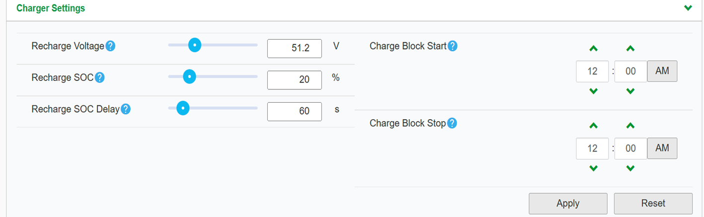
| PARAMETER | VALUE | |
CHARGER SETTINGS | ||
| RECHARGE VOLTAGE | 51.2V | |
RECHARGE SOC | 20% | |
| RECHARGE DELAY | 60S | |
BATTERY SETTINGS | ||
| BATTERY TYPE | LI-ION | |
CHARGE CYCLE | EXTERNAL BMS | |
SOC CONTROL ENABLE | ENABLED | |
BATTERY BANK CAPACITY | 314aH per eBoost | |
Maximum Charge Rate | 100% | |
Maximum Bulk Charge Current | 180A per eBoost | |
maximum absorption charge current | 180A per eBoost | |
Maximum Float Charge | 180A per eBoost | |
Default Battery Temperature | WARM | |
| Absorption TIme | 3600 | |
Bulk/Boost VOltage | 55.2V | |
| Absorption Voltage set Point | 55.2V | |
Maximum Discharge Current | 250A per eBoost | |
Maximum Discharge Time Interval | 8s | |
low Battery Cut Out | 48V | |
low Battery Cut Out Delay | 10s | |
low Battery Cut Out hysteresis | 2 | |
low Battery Cut Out warning offset | 2 | |
high Battery Cut Out | 58V | |
| CHARGE CYCLE TIMEOUT | 1440s | |
| high SOC COT OUT | 99% | |
high SOC COT OUT delay | 2s | |
low SOC COT OUT | 15% | |
low SOC COT OUT delay | 60s | |
Victron
Setup steps
Outback inverter integration guide
Share Your OpticsRE online monitoring with Fortress Power. Sharing OpticsRE with Fortress Power
Log into OpticsRE and Click on “My Profiles” in the side menu. Click on the Gear icon next to the site name
Unpack batteries and check voltage
- Unpack the batteries and turn each battery on by itself.
- Note the voltage of each battery and serial number. The serial numbers are useful during warranty submittal.
- The batteries must be within +/-0.5V of each other before commissioning. Groups of 4 batteries or more may require a narrower voltage range to commission properly.
- Turn off the batteries and install them in parallel.
Notes
If the battery voltages are significantly different, one technique is to finish battery installation and only turn on the lowest voltage battery using the push button. Charge the battery, and when the charging voltage is ~0.2V above the resting voltage of the next lowest battery, turn it on too. Proceed until all batteries are turned on and at the same voltage level. If the batteries are below 51V, keep charging amperages below 10A per battery.
If the batteries are slightly more than +/-0.5V from each other, turning on the highest voltage batteries will only reduce their voltages, and turning on the lowest voltage batteries will only lower the highest voltage. Likewise, turning on the lowest voltage batteries as a group will raise the lowest voltage. Then, all the batteries can be turned on within a 0.5/V difference.
Use of the Fortress firmware update tool can help speed up commissioning times. Fortress installers should request a firmware update tool by filling out a support ticket at https://support.fortresspower.com
Radian Inverter Settings
Inverter | 80% DoD, 6000 cycle |
Absorb Voltage and Time | 55.2 Vdc/ 2.0hr |
Float Voltage and Time | 54.4 Vdc / 0.0 hr *only float with w/inverter if charge controllers unavailable |
Re-float Voltage | 52.4 Vdc *Increase by 1V if charge controllers unavailable |
Re-Bulk Voltage | 51.2 Vdc *Increase by 1V if charge controllers unavailable |
AC Input Mode | Grid Tied (default, adjust as needed) |
AC Charger Limit in AC | eBoost:180Aac per battery |
Low Battery Cut- Out Voltage | 51V *user adjustable |
LBCO Delay | 130 seconds *user adjustable |
Low Battery Cut-in Voltage | 51.8 *user adjustable |
High Battery Cut-Out Voltage | 56V |
HBCO Delay | 10 seconds |
High Battery Cut-in Voltage | 55.2V |
SellRE (Offset) Voltage Max | 51.6V for “zero-outflow”, 53.6V for selling at “100% full” |
Temp Sensors | Do not use temperature sensors / reduce any temperature coefficients to as close to zero as allowed |
FM60/80/100 Charge Controller Settings
Charge controller | |
Absorb Voltage and Time | 55.2, 1 hours |
Float Voltage | 54.4 |
Rebulk Voltage | 52.5 |
DC Current Limit | eBoost: 180A per battery ÷ # of controllers |
Absorb End Amps | 1A |
FlexNET DC Settings
FLEXnet DC (FN-DC) | If FLEXNET DC display voltage is not within 0.1V of inverter terminal voltage, calibrate Outback equipment |
| Battery Amp hour | eBoost:314Ah per battery |
| Charged Voltage | 54.0V |
| Charged Time | 15 minutes |
| Charged Return Amps | 1A |
| Battery Charge | 96% |
| Relay Invert Logic | No *User adjustable |
| Relay Voltage | High = 53.8 ; Low = 51.2 *User adjustable |
| Relay Delay | High = 1, Low = 0 *User adjustable |
| MATE3/MATE3s | |
| FLEXnet DC Advanced | Low SOC Warning = 20% *User adjustable |
FLEXnet DC Advanced | Critical SOC Warning = 10%*User adjustable |
Calibrating Outback Systems
Calibrating the battery means charging the battery 100% full and confirming the battery resting voltage is above 54V. This can be done onsite or remotely.
Calibration is not a regular task. Good times to calibration are:
- System commissioning
- Occasionally when batteries are kept 80-100% full.
- Deep discharge recovery.
- Extended periods of overcast / low production days.
- Anytime when the % state-of-charge says 100% but battery voltage is below 54V.
Conforming calibration is easiest to do online but can be done onsite.
- Go to OpticsRE.
- Reduce all system loads and charging to a bare minimum, including charge controllers.
- Determine the battery voltage on the inverter terminals.
- Calibrate the charge controllers to match the inverter terminals.
- Determine if the FlexNET DC also needs calibration and follow this link for further instructions:
Related Articles
eBoost Installation Manual
1. Abreviations 2. Change Log VERSION CHANGE DESCRIPTION EBM-WV20251121 eWay Lite dimensions added R1-R2 Relay cable installation added for paralleling. Added eWay lite Knockout modification Added Parallel configurations include do not share battery. ...eBoost - Victron Integration Guide
TesteBoost - Sol-Ark Integration Guide
TesteBoost Installation Manual
Hook it upeBoost - Envy Commissioning
Easier than the other integrations