eBoost Installation Manual
1. Abreviations
2. Change Log
VERSION | CHANGE DESCRIPTION |
EBM-WV20251121 | eWay Lite dimensions added |
R1-R2 Relay cable installation added for paralleling. | |
Added eWay lite Knockout modification Added Parallel configurations include do not share battery. | |
3. Introduction
3.1 About Fortress Power
Our mission is to provide compact, user-friendly, and affordable energy storage solutions using the latest technology for all homes and businesses. Fortress Power solar energy storage batteries can easily integrate with new and existing PV systems and work with a wide range of existing inverter and charge controller manufacturers for ease in system design.
Contact Information
Corporate Headquarter Address: 2010 Cabot Blvd West, STE L
Langhorne, PA 19047 United States
Website: www.fortresspower.com
Email: sales@fortresspower.com
Phone: US: (877) 497-6937
LATAM: (215) 710-8960
3.2 Warranty Support
Unless otherwise submitting a Fortress warranty through the Guardian hub, please submit your eBoost warranty here:
Beyond this product manual, you may also find our inverter guides useful to system installation and commissioning:
Beyond that, please find additional resources within our Support Portal https://support.fortresspower.com/portal/en/kb
- Create a support ticket.
- Product Manuals
- Firmware Updates
- Warranty Submittal
- System Design
- Application Notes
- Scheduled Meetings
- Accessories
4. eBoost Introduction
The eBoost Battery is an advanced energy storage solution designed to cater to both residential and commercial energy needs. This battery is manufactured by Fortress Power, known for its innovative approach to providing reliable and efficient energy storage solutions.
The eBoost battery is available in various configurations to build into DC ESS system, including 16 kWh, and 32 kWh options and scalable to 256kWh, making it a solution that can be tailored to different energy requirements. The nominal voltage of the battery is 51.2V and can operate within a voltage range of 41.6V to 57.6V, offering flexibility in various applications.
Technology and Features:
Benefits and Applications
The eBoost battery is designed to provide numerous benefits across various applications:
- Energy Independence and Off-Grid: It allows homeowners and businesses to store excess energy generated from renewable sources like solar panels, reducing reliance on the grid and providing energy independence.
- Backup Power: The battery provides a reliable source of backup power during grid outages, ensuring continuous operation of essential systems.
- Peak Shaving: By storing energy during off-peak hours and discharging during peak demand, the eBoost battery helps in reducing electricity costs and increasing your return of investment.
- Grid Export, Net Metering and VPP: Allow the eBoost to discharge/charge energy to and from the grid during high demand hours and getting credit/money on your energy bill allowing savings and bankability.
- Safety and Longevity: With a cycle life of 8000 cycles at 70% End of Life (EOL), and a 10-year warranty the eBoost battery offers long-term reliability, providing peace of mind.
5. PRODUCT SPECIFICATIONS AND SYSTEM DESIGN
5.1 Datasheet
5.2 System Sizing
Please refer to our sizing
guide and warranty letter for appropriate sizes between various inverter models and the eBoost.
https://support.fortresspower.com/portal/en/kb/articles/minimum-battery-sizing . Under no circumstance should you install
an inverter with charging capacity
greater than 250A per eBoost even
if you intend to limit the charge or discharge
capacity of the inverter either manually or digitally.
| INVERTER | EBOOST 16 OPEN-LOOP | EBOOST 16 CLOSED-LOOP |
FORTRESS POWER ENVY 8KW | 1 | 1 |
FORTRESS POWER ENVY 10KW | 1 | 1 |
FORTRESS POWER ENVY 12KW | 1 | 1 |
FORTRESS POWER ENVY DUO 21 | 1 | 1 |
FORTRESS POWER SOLO 6.5 KW | 1 | 1 |
FORTRESS POWER EDGEON DUO 9 | 1 | 1 |
FORTRESS POWER EDGEON DUO 15 | 1 | 1 |
SCHNEIDER ELECTRIC XW PRO 6848 | 1 | 1 |
SCHNEIDER ELECTRIC XW+ 6848 | 1 | N/A |
SCHNEIDER ELECTRIC XW+ 5548 | 1 | N/A |
SCHNEIDER ELECTRIC SW 4048 | 1 | N/A |
OUTBACK POWER RADIAN 8048A | 1 | N/A |
OUTBACK POWER RADIAN 4048A | 1 | N/A |
OUTBACK POWER VFXR 3648A | 1 | -- |
OUTBACK POWER FXR 3048A | 1 | N/A |
SOL-ARK 5K | 1 | 1 |
SOL-ARK 8K | 1 | 1 |
SOL-ARK 12K | 1 | 1 |
SOL-ARK 15K | 1 | 1 |
STUDER INNOTEC AJ 400-48 | 1 | 1 |
STUDER INNOTEC AJ 700-48 | 1 | 1 |
STUDER INNOTEC XTS 1400-48 | 1 | 1 |
STUDER INNOTEC XTS 2600-48 | 1 | 1 |
STUDER INNOTEC XTS 4000-48 | 1 | 1 |
STUDER INNOTEC XTS 6000-48 | 1 | 1 |
STUDER INNOTEC XTS 8000-48 | 1 | 1 |
MAGNUM / SENSATA MS 4448 | 1 | - |
MAGNUM / SENSATA MS 4048 | 1 | - |
VICTRON ENERGY QUATTRO 48/3000/35 | 1 | 1 |
VICTRON ENERGY QUATTRO 48/5000/70 | 1 | 1 |
VICTRON ENERGY QUATTRO 48/10000/140 | 1 | 1 |
VICTRON ENERGY QUATTRO 48/15000/200 | 1 | 1 |
6. Safety
6.1 Symbols
Symbol | Meaning | Symbol | Meaning |
Caution! Failure to observe the warning may result in injury | Read operator's manual carefully before performing any operation on the devices | ||
Risk of electrical shock, fire, or damage | Read operator's manual | ||
Explosive material | Electrical Ground (connector) | ||
Battery charging | No smoking or open flame | ||
Heavy object | No children allowed | ||
Do not connect positive and negative terminals in reverse | Important instructional note | ||
Components of the product can be recycled | |||
This symbol indicates that a lithium-ion (Li-ion) battery is inside the product and should be disposed of or recycled properly | |||
this symbol indicates that the product shall not be disposed of as household waste and should be delivered to a designated collection facility for recycling. Proper disposal and recycling can help protect the environment. For more information about the disposal and recycling of this product, contact your local community, disposal service, or dealer | |||
| Symbole | Signification | Symbole | Signification |
Attention! Le non-respect des messages d'avertissement peut entraîner des blessures | Lisez attentivement le manuel de l'opérateur avant d'effectuer toute opération sur les appareils | ||
Risque de choc électrique | Lisez le manuel de l'opérateur | ||
Matières explosives | Mise à la terre électrique (connecteur) | ||
| Charge de la batterie | Ne pas fumer ou flamme nue | ||
Objet lourd | Aucun enfant n'est autorisé | ||
Ne connectez pas les terminaux positifs et négatifs à l'envers | |||
Les composants du produit peuvent être recyclés | |||
Ce symbole indique qu'une batterie lithium-ion (Li-ion) se trouve à l'intérieur du propduit et doit être éliminée ou recyclée correctement | |||
Ce synbole indique que le produit ne doit pas être éliminé en tant que déchets ménagers et qu'il doit être livré à une installation de collecte désignée pour être recyclé. Une élimination et un recyclage appropriés peuvent aider à protéger l'environnement. Pour plus d'informations sur l'élimination et le recyclage de ce produit, contactez votre communauté locale, votre service d'élimination ou votre revendeur. | |||
6.2 Safety Precautions and Instructions
Damage to the product may lead to a leakage of electrolyte or flammable gas. During installation of the battery, the utility grid and solar input must be disconnected from the Battery Pack wiring. Wiring must be carried out by qualified personnel. The battery pack contains no user serviceable parts. High voltage or current is present in the device. The electronics inside the Battery Pack are vulnerable to electrostatic discharge. Observe the following precautions:
Risks of explosion
Do not subject the battery pack to strong impacts. Do not crush or puncture the battery pack.Do not dispose of the battery pack in a fire.Risks of fire
Do not expose the battery pack to temperatures more than 140°F (60°C). Do not place the battery pack near a heat source such as a fireplace or open flameDo not expose the battery pack to direct sunlight.Do not allow the battery connectors to touch conductive objects.Risks of electric shock
Do not disassemble the battery pack.Do not touch the battery pack with wet hands.Do not expose the battery pack to moisture or liquids. Keep the battery pack away from children and animals.Risks of damage to the battery pack
Do not allow the battery pack to come in contact with liquids. Do not subject the battery pack to high pressures.Do not place any objects on top of the battery pack.
IMPORTANT NOTE: Circuit Breakers, Disconnects and Fuses should be employed throughout the energy storage system and generation installation to isolate effectively and protect all components against faults, short circuits, polarity reversals or failure of any component in the installation.
Fuses, breakers, wiring ratings and values should be determined by established standards and evaluated by certified electricians, licensed installers, and regional code authorities. The eBoost B a t t e r y Management System (BMS) alone will not protect the batteries from these extreme electrical events. Failure to adhere to proper installation protocol will void the warranty.
Most batteries pose some risk of shock or sparking during the installation and initial wiring and connection process. Wearing insulated gloves, clothing and footwear and using electrically insulated tools are required when working with the eBoost. Cover or remove jewelry or conductive objects (metal bracelets, rings, belt buckles, metal snaps, zippers, etc.) when working with any electrical or mechanical device. Cover or restrain long hair and loose clothing when working with any electrical or mechanical device. CAUTION! Do not disassemble or modify the battery. If the battery housing is damaged, do not touch the exposed contents
6.3 Temperature considerations
Do not charge the battery when the ambient temperature is freezing or below. Discharge current at sub-freezing temperatures should also be significantly reduced.
Recommended operating parameters of charger/Inverters For 3,000 Cycles:
- Internal battery temperature range: 32 F to 120 F (0 °C to 49°C) without close-loop communication.
- Bulk voltage and absorb voltage should be set to 55.2V if no battery-inverter communication is available.
Recommended operating parameters of charger/Inverters For 8,000+ Cycles:
- Operating temperature range: 50°F to 110°F (0°C to 60°C) per Fortress Power recommend charge and discharge inverter configuration
6.4 Transportation and handling
- Do not knock, drop, puncture, or crush the battery.
- Do not expose battery to flames, incinerate or direct sunlight.
- Do not open the battery case or disassemble the battery.
- Do not lift battery by the terminal cables.
- Do not vibrate the battery.
- Do not expose the battery to water or other fluids.
- Do not expose battery to open flame.
- Do not place the product nearby highly flammable materials, it may lead to fire or explosion in case of accident, Store at cool and dry place.
- Do not store in greenhouses and storage areas for hay, straw, chaff, animal feed, fertilizers, vegetables, or fruit products.
- Store the product on a flat surface; A ventilated area is strongly recommended for handling the product.
- Store the product out of reach of children and animals.
- Store the product where there is minimal dust and dirt in the area; do not transport battery upside down or with the terminals towards the ground.
- Batteries must be discharged to 30% state of charge or 51.2V resting voltage before transporting
6.5 Response to emergency situations
The battery pack consists of multiple batteries and a sophisticated Battery Management System that is designed to prevent hazards resulting from failures. However, Fortress Power cannot guarantee their absolute safety.
Leaking Batteries:
- If the battery pack leaks electrolyte, avoid contact with the leaking liquid or gas. If a person is exposed to the leaked substance, perform the actions described below immediately.
- Inhalation: Evacuate the contaminated area and seek medical attention.
- Contact with eyes: Rinse eyes with flowing water for 15 minutes and seek medical attention.
- Contact with skin: Wash the affected area thoroughly with soap and water and seek medical attention.
- Ingestion: Induce vomiting, and seek medical attention.
Fire
- In case of fire, make sure that an extinguisher is available near the battery pack. If possible, move the battery pack to a safe area before it catches fire.
Note: Fire Extinguisher
Water, carbon dioxide, dry chemical powder and foam are the most effective means to extinguish a Lithium Ferrous Phosphate (LFP) battery fire.
Use an ABC Fire extinguisher, if the fire is not from battery and has not spread to it yet.
6.6 Storage
Store batteries away from direct sunlight and in locations with temperatures ranging between 0°C and 35°C (32°F to 95°F) to avoid exposure to high temperatures.
- Turn off the battery during long-term storage to reduce the self-discharge rate, which is about 1% when the SOC is above 20%.
- Maintain a Relative Humidity (RH) level between 5% and 95% in a dry and clean indoor environment. Prevent contact with corrosive materials and keep away from fire and heat sources.
- For storage durations exceeding one month, ensure the battery's State of Charge (SOC) is maintained between 30% to 50%. It is crucial to charge and discharge the battery every six months to maintain health.
- Regularly check the battery every 3 months to ensure the SOC remains above 20% (greater than 51.2V). If it falls below this level, charge the battery up to 51.8V before returning it to storage.
- When placing systems into storage, set the SOC to 30~50% and periodically verify that it does not drop below 20%.
If you expect the battery to be left unattended for extended periods, set a higher battery cutoff voltage as a precaution. This is particularly important if the power supply is critical, and the charging sources (like solar panels) may be obstructed by snow or dust. In such scenarios, installing a backup generator with an AutoStart feature is advisable. Note that the inverter and battery management system may impose a minor load on the battery, potentially depleting it over long durations without any charging sources. Following these guidelines will help ensure your battery's longevity and reliability, even during extended storage periods.
6.6 Tools and materials
The following tools and materials are required and are not included:
OSHA approved personal protective equipment, Safety Shoes, Safety Glasses, Insulated Gloves, and Weightlifting Belt.
Bendable Screwdriver extension
Metric hex socket set
Metric wrench set
Phillip and Flat Head Screwdriver Set.
Power Drill and wood or and concrete drill bit set
Hand Truck (Optional)
Positive and negative battery cables, we recommend copper cable starting at 3/0 for runs of less than 10ft. Please refer to your adopted version of the National Electric Code or Local Authority Having Jurisdiction for more guidance (not included).
UL Battery Cable & Positive and Negative Terminal lugs. Note that the eWay ring terminal hole size is 3/8in.
Wire Stripper and Crimper (Up to 4/0)
7. Unboxing check list
7.1 eBoost battery
7.2 eBoost eWay (sold separately)
8. Battery specifications
8.1 Dimensions and definitions
8.1.1 eBoost Battery
8.1.2 eBoost eWay (sold separately)
Cable requirements | ||||
Inverter | Cable Size | Voltage | Qty | eWay Busbar Torque Specifications |
ENVY 12kW | Up to 4/0 | 600 | 1 Pair per eWay | 6.2lbf-ft (8.5Nm) |
ENVY 10kW | Up to 3/0 | 600 | 1 Pair per eWay | 6.2lbf-ft (8.5Nm) |
ENVY 8kW | Up to 3/0 | 600 | 1 Pair per eWay | 6.2lbf-ft (8.5Nm) |
eWay-eWay | Up to 4/0 | 600 | 1-2 Pair per eWay | 7.37-8.85lbf-ft (10~12) Nm |
KNOCKOUT HOLE SIZE (IN) | CONDUIT SIZE (IN) |
A 0.87 | ½ |
B 1.11 | ¾ |
C 1.38 | 1.00 |
D 1.73 | 1 ¼ |
E 2.00 | 1 ½ |
F 2.48 | 2.00 |
8.1.2.1 eWay Sections
Power Switch
Allows user to power on the eBoost by press and hold the power button for 1 second. At the same time provide a method to select the inverter protocol by holding the push button for 2 seconds. Press and hold for 10 seconds to power off.
E-Stop Feature
A safe means of disconnecting the battery from a 48V HYBRID inverter and disabling battery voltage output. Lockout hole measures 0.24”. When paired with the Envy True 12kW/10kW/8kW it allows the option of providing complete ESS disconnection when enabling Rapid Shut Down (RSD) allowing first responders to safely mitigate any hazardous event within the property.
Guardian Antenna Port
Allows user to extend the Guardian WIFI capability. Use the antenna included with the Guardian.
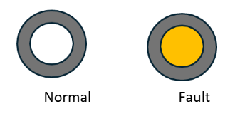
Backlight Status Indicator
Serves to indicate Normal battery operation or a Fault. When White, the system is in Normal function, When Yellow there is a fault present in the battery
8.2 Communication
8.2.1 LED status definition
8.2.2 Communication Board
8.2.2.1 Port definition
| PIN | COLOR (B Format) | ASSIGNMENT | FUNCTION |
1 | White-Orange | Can1_H | BAT-BAT communication Guardian CAN Communication n/a |
| 2 | Orange | Can1_L | |
| 3 | White-Green | Can2_G | |
4 | Blue | Can2_H | PCS CAN communication n/a |
| 5 | White-Blue | Can2_L | |
6 | Green | RS485G1 | |
7 | White-Brown | RS485A1 | PCS 485 Communication |
8 | Brown | RS485B1 |
8.2.3 Inverter Communication protocol
To select the inverter protocol to achieve closed loop communication, you must press and hold the power button for 5 seconds, then release it. Immediately the LED 6&7 will start flashing following the current inverter protocol status. In this stage, press the button once until you select the correct protocol as shown in the images below.
9. Spacing requirement
9.1 Minimum spacing requirement
9.2 Acceptable but not limited Installation Configurations
Floor Mounted
Envy 12k/Envy Duo 21 right side Installation measurements (Floor Mounted) |
Envy 8k/10k right side Installation measurements (Floor Mounted) |
Wall hanged
This configuration includes the option of bolting the included eBoost wall bracket in the wall. Make sure the Power Switch or the PV DC disconnect from the Inverter does not surpass 6’7” per NEC Code.
9.3 Unacceptable configurations
One eBoost 16kWh with two Envy inverters /Two front mounted batteries | Notes | |
Figure A. The eBoost maximum discharge current is 250A continuous. Each Envy 8k/10k/12k/Envy 21 Duo maximum continuous output is 167A/210A/ 250A/250A Respectively Use always 1:1 ratio when paring an eBoost with any model of the Envy inverters. Figure B. Do not mount a battery in front of another eBoost when hanging the eBoost on the wall as this can cause damage to both the wall and the battery. | ||
9.4 Maximum wall hanged height requirements
Consider NEC CODE SECTION 404.8(A) when wall mounting the eBoost. Please follow the guidelines below. DO NOT INSTALL the battery system above the stipulated Heigh. The height reference is taken from the highest disconnect per the NEC code
Wall hanged with Envy 12k/Envy Duo 21k (Measurement in inches) | Wall hanged with Envy 8k/10k (Measurement in inches) |
Envy 12k/Envy Duo 21 right side Installation measurements (Wall hanged) |
Envy 8k/10k right side Installation measurements (Wall hanged) |
10. Installation
10.1 Preinstallation
- Select the Mounting Location:
- Ensure the surface where the mounting base will be installed is clean, dry, and level.
- Measure and mark the mounting points according to the dimensions of the base.
- The eBoost Battery should not be installed in direct exposure to the sun (South facing with reference to the Sun).
2. Safety Considerations:
- Wear safety glasses and gloves during installation to protect against debris and sharp edges.
- Ensure the installation area is free from obstructions and that there is adequate lighting.
- Clear the area where the battery module will be installed.
3. Weight Considerations
Follow OSHA standards when installing this battery. Each battery module weighs 308.lbs including the eWay.
Ensure the floor is level and capable of supporting the weight of the battery.
Use a lifting machine when wall mounting the battery. Optionally, the battery module may be wheeled in place of the installation site and anchored to the wall with L-SHAPED brackets
We highly recommend using a hand truck or other machinery to move batteries from the transport vehicle to the installation site. Make sure that the arrows on the box are facing upwards before opening. This will facilitate installation procedure moving forward. Open the box, remove protective foams, plastic bag, contents and slide the battery outwards.
10.2 Mechanical installation
10.2.1 Floor standing installation
1. Resurfacing the floor
2. Install the system with wall mounted configuration.
Instructions:
1. Clean Area
- Clean Area and remove any debris, tools from the floor in the installation area.
- Ensure the installation area is well lit and free from obstructions.
2. Attach the Brackets
- Use the provided hardware to attach the brackets to the mounting base.
- Align and screw the two wall fitted brackets to the designated positions.
- Tighten the hardware, place the battery against the wall and mark the holes to be drilled.
3. Align the template
- Position the mounting
template (carton board) against the wall and rest the bottom to the L-shaped brackets.
- Use a level to ensure that the template is properly aligned vertically and horizontally. Make minor adjustments to the position of the template as necessary.
- Using a marking tool, mark the locations of the mounting holes on the wall or surface where the inverter will be installed.
- Identify with an x the spot in which the mounting holes must be drilled. Remove the template and drill holes. If mounting on a concrete wall, use a drill with a masonry bit to create holes for anchors
Battery Installation with Envy on top
10. Connect the Electrical and communications cables between the eWay and the Envy inverter
11. Finally, secure the batteries with the red knobs on the battery legs.
Operation of the Red Leveling Knobs
Each battery support leg is equipped with an integrated caster wheel for mobility and a red twist-style leveling knob for height adjustment and stabilization.
- Mobility Mode
- When the red knob is rotated clockwise, the adjustable foot retracts upward, transferring the load onto the caster wheels. This allows the battery cabinet to be easily moved or repositioned.
- Stabilization Mode.
- By rotating the red knob clockwise, the adjustable foot extends downward until it makes firm contact with the floor. Continued turning raises the cabinet slightly off the caster wheels, shifting the weight fully onto the stationary legs. This prevents any rolling or unwanted movement.
- Fine Height Adjustment – The threaded mechanism inside the leg allows for precise height control. This ensures the cabinet can be leveled on uneven floors, improving stability and reducing mechanical stress on the frame.
10.2.2 Floor standing installation (front battery paralleling)
10.2.3 Connection overview
One eBoost Battery and Envy Inverter Electrical Connection Overview
When operating
with one eWay, keep the terminator plug placed in its original
position. Plug one side of the BAT-PCS
cable into the RJ45 ports of the
Communication board and the other side into the inverter BAT COM port. RSD
features include complete
system shut off by disconnecting the batteries voltage
output, Disabling PV Voltage, and Load Output per
NEC 2023 Code. To achieve this, Follow the connections in the above image.
Two or more eBoost Battery and Envy Inverter
Electrical Connection Overview
Remove the terminator from the first eWay and place battery to battery communication. Make sure that the secondary eWay keeps the terminator connected in its original port. Repeat this process with batteries connected in parallel by connecting the Battery -Battery RJ45 Cables in daisy chain sequence starting with the first battery to the last. Place the Resistive RJ45 plug into the terminator Port of the last secondary battery following chronological sequence starting with the Primary Battery. For More details of parameter settings, please refer to the Fortress Power Envy 12kW/10kW/8kW Manual.
11. Commissioning
For Commissioning batteries where multiple eWay are in parallel, please go to the “Commissioning in Parallel” section.
1. Turn the battery breaker inside the inverter. See below.
2. Turn the RSD Switch to the ON position
3. Verify by applying a voltmeter at the eWay internal busbar.
4. Press the Power button.
Make sure to select the correct inverter protocol by holding the power button
for 5 seconds after initiating the battery.
5. Make sure that the Guardian is powered on and follow the Quick Start Guide starting with step 6.
6. Scan the QRCODE on cover page of the manual to download the Guardian APP.
Commissioning multiple eBoost batteries in Parallel
For a maximum battery bank size of 256kWH, up to 16 eBoost 16kWh batteries can be connected in parallel. All wires should be an appropriate gauge and constructed to manage the loads that will be placed upon them. A qualified installer should understand this and must adhere to industry standards and published electrical guidelines. The storage capacity and total permissible charging and discharging amperage are increased by parallel arrangement. The overall voltage is not changed. Instead, the available amperage from the system is increased with each additional parallel battery. Double Check if battery-battery communication cable is connected and secured.
Please follow this procedure to commission eBoost 16kWh batteries in parallel:
1. Turn all DC Breakers on the ON position (Hybrid Inverter, Charger Controllers)
2. Turn the RSD Switch to the ON position as shown in above figure 2.
3. Turn on the first battery’s Power Switch (the first battery is the one communicating with inverters). Do not turn on the power button of the other batteries. If all cables are correctly connected, LED will commence booting sequence, and the other batteries will engage by energizing.
4. Measure Voltage inside the eWay busbar to confirm.
5. Press the Power button. Make sure to select the correct inverter protocol by holding the power button for 5 seconds after initiating the battery. Verify by applying a voltmeter at the eWay internal busbar.
For inverter-specific settings, visit https://www.fortresspower.com/support for the most recent integration manual for each specific inverter brand.
12. Settings
12.1 Amperage settings
- Do not use unqualified equipment for charging and discharging, please follow the correct instructions for use.
- Do not discharge the battery when the battery is depleted.
- Do not charge or discharge batteries that are hot, deformed, or leaking.
- The output cable length of the battery should be less than 10 meters long.
- Do not connect a power and load that exceeds the power level to the two ends of the battery.
- Do not mix different batteries. Different manufacturers, chemistry, models, and lifespans cannot be paralleled.
12.2 Charging voltage
Without battery-inverter communication, eBoost batteries should be charged at 54.4V. With battery-inverter communication, eBoost batteries this voltage may be increased according to the published inverter guides: https://www.fortresspower.com/inverter-guides
12.2.1 Low battery cut-off voltage
The eBoost battery is below a 20% state-of-charge when its resting voltage is below 51.4V In order to keep the inverter and battery system powered up while waiting for a charge, this is the recommended low battery cut-off voltage. It is appropriate to lower this to 51V if using a generator or grid charge to automatically maintain or charge the battery at 51.4V or above. Many older battery inverters cannot program a low battery cut-out voltage above 48V. The eBoost has a safety feature that will cut around this voltage level if necessary. If you regularly deep discharge the eBoost down to 48V, please increase your battery size or upgrade your inverter to maintain warranty compliance.
12.2.2 Charging and discharging amperage
Precautions should be taken when adding charging sources which are not controlled by a single inverter or control system (Ex. using different manufacturer's DC charge controllers and inverters, solar + wind inverters, EV chargers etc.) to ensure the total system charges or discharges the battery within its specification. Controllers do not charge the battery concurrently, when and if their combined charge current totals are greater than the charge current of the combined battery bank.
Take additional extra precautions when using wind power to charge the battery, or if the inverter and charge controllers are not the same manufacturer.
12.2.3 Charging notes
If the following scenarios occur, the battery must be charged before use, otherwise the battery damage caused is not covered by the warranty:
- The battery has not been powered on or otherwise discharged without any charging sources available.
- The battery has been turned off for a long period during transportation or storage.
- The battery has been deeply discharged and reached under-voltage protection status.
- The battery has been aggressively recharged during deep discharge conditions through bypassing the BMS.
- The battery has been recharged during freezing condition through bypassing the BMS.
- Bypassing the BMS is not allowed without logging a support ticket with Fortress Technical Support at https://support.fortresspower.com
12.2.4 Discharging notes
- Do not regularly discharge battery below 51V, 20% SoC. This capacity should be reserved for power outages and idling the load until a charging source can be applied.
- Do not discharge battery at rates greater than maximum continuous current.
Parameter set up guide for Charger/Inverter
Unless explicitly stated in Fortress inverter guides or contrary to the above charging amperages and voltages, charge controller and inverter settings must be programmed per the manufacturer’s recommendations. Consult the manufacturer’s manuals and/or access technical support. To achieve extended life cycles and to comply with the Warranty, the following guidelines should be followed:
Understanding Charge Stage
- Bulk Charge: Charge at Constant Current (CC) to Bulk/Absorb Voltage.
- Absorption Charge: Maintain Constant Bulk/Absorb Voltage (CV). Note - if the battery is not reaching 100% capacity, it is allowable to adjust this voltage from 54.4V to 55V. Any higher charging voltage must be explicitly stated a Fortress inverter guide specific to that brand of inverter.
- Unless otherwise stated in a Fortress inverter guide, keep float voltages at 54.4V or less to maintain warranty compliance. While most end users will want to enable a float mode of operation if available to keep batteries at 100%, it is healthier for the battery only to use the bulk/absorb cycle - which allows the batteries to exercise daily.
13. Decommissioning
At the End of Cycle Life retained capacity is equivalent to 70% Year 1 Capacity. eBoost contains scrap material useful to recycling. Dispose of the battery at a local recycling center or ship back to Fortress Power. Transport end-of-life batteries at 30% state-of-charge, <52V resting.
13.1 Key points summary
- Each Fortress Lithium Battery contains circuitry that protects the Lithium Ferro Phosphate cells from overcharging, over-discharging, and excessive load amperage. If the values specified are exceeded, the battery will enter a protective shut down state. In some cases, this may result in the need to reinitialize an inverter charger or other pieces of equipment in the installation. In other cases, the inverter’s system settings may be saved within the inverter memory storage and will not need to be reset. This is not an absolute standard but is common among most inverter chargers. Check your inverter manufacturer specifications.
- Although each Fortress Lithium Battery contains circuitry that protects the Lithium Ferro Phosphate cells from overcharging, over-discharging and excessive load amperage, Fortress Lithium Batteries must always be installed with a charge controller and appropriate settings to protect the batteries from open PV and other high voltage sources. Fortress Lithium Batteries alone will not protect from extreme electrical phenomena.
- GRID TIED SYSTEMS: Once the Fortress Lithium Battery has been installed, turn on the entire system to test. Once testing has been completed, please disconnect the batteries from the load center until your local Utility Inspector is ready to turn on the entire system. The charge controllers and inverter monitoring systems can drain the Fortress Lithium Batteries over an extended period when the entire system is not fully operational due to the electrical draw of the system components.
- OFF GRID SYSTEMS: Do not connect the Fortress Lithium Batteries until the entire system is ready to turn on and is fully operational.
13.2 Heating element operation
Temperature | Heating elements status (125W) | Charge/discharge status |
≤ -4°F (-20°C) | OFF | OFF/OFF |
-4°F (-20°C) <TMIN≤32° F(0°C) | ON | OFF/ON |
32°F(0°C) <TMIN≤41°F(5°C) | ON (Stop heating @ Tmin>50°F (10°C) | ON/ON |
TMIN>41°F(5°C) | OFF | ON/ON |
VMIN<45V OR SOC<20% | OFF | ON/ON |
The integrated heaters are energy-efficient, activating only when necessary, to preserve battery life and enhance overall system efficiency.
14. Contact information
Related Articles
eBoost Installation Manual
Hook it upeBoost Battery - Inverter Integration Guide
Important notice This Quick Guide does not exempt the installer or User from reading each product manual. Failure to do so may risk damaging both Fortress Power equipment and other manufacturers and void warranty. Abbreviations Connection diagrams ...VIDEO: eBoost Unboxing and Installation
eBoost - Victron Integration Guide
TesteBoost - Envy Commissioning
Easier than the other integrations