eForce Inverter Integration Guide
Important Notice
This Quick Guide
does not exempt
the installer or User from reading each product
manual. Failure to do so may risk damaging
both Fortress Power equipment and other
manufacturers and void warranty.
Connection Diagrams
Connection Overview
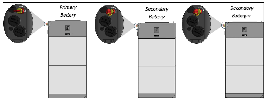
Parallel Connection Overview
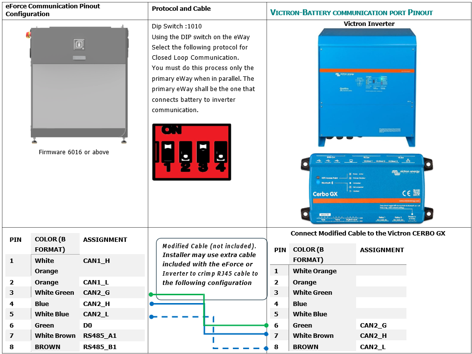
Closed loop and Pinout
Definitions
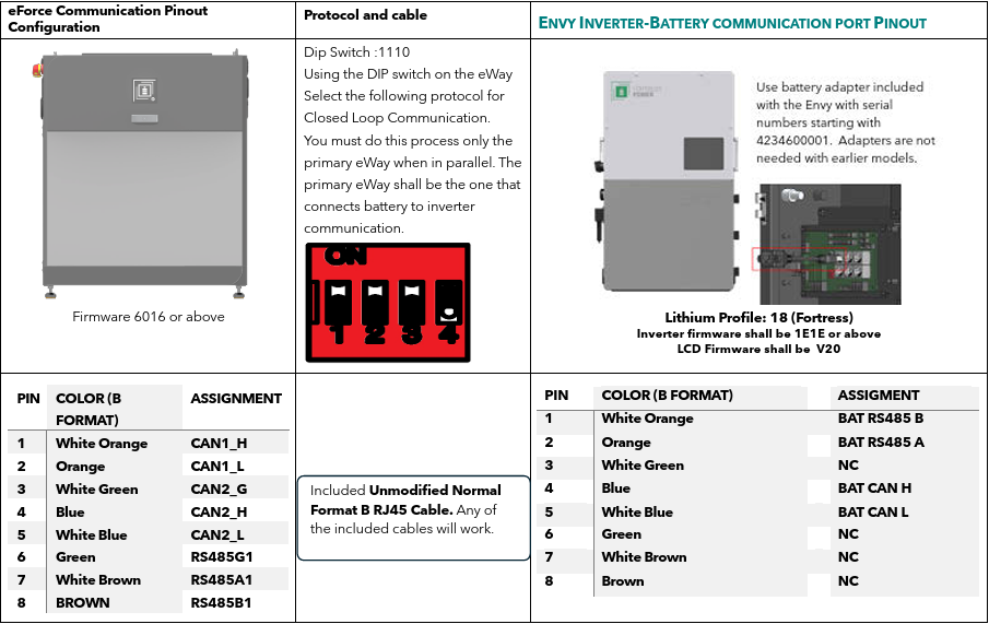
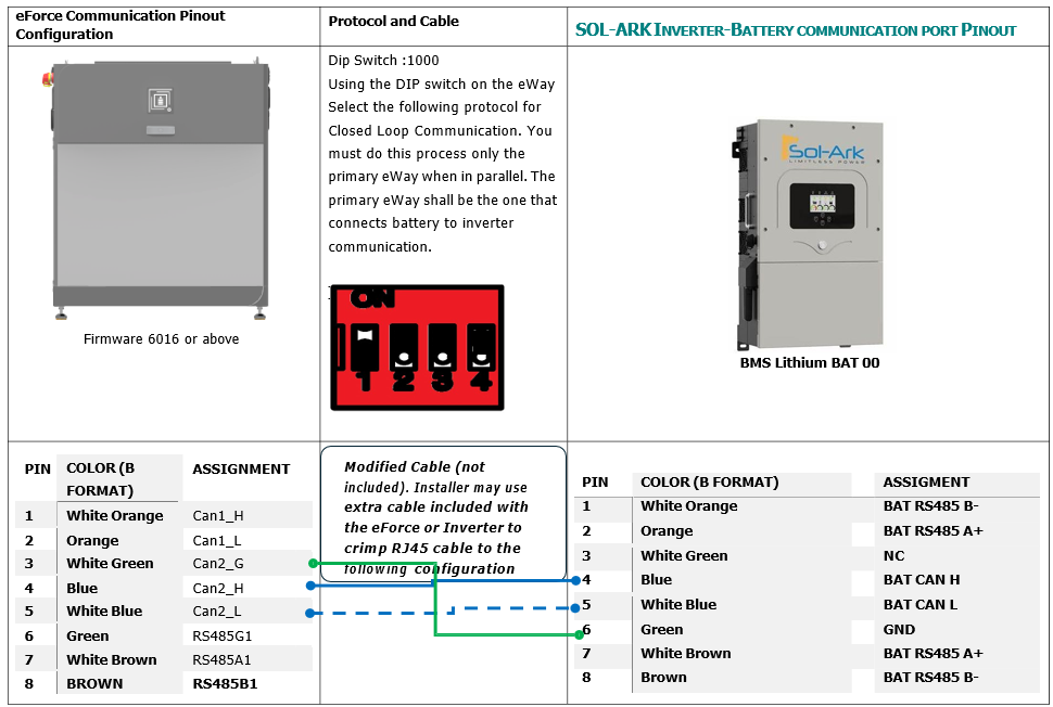
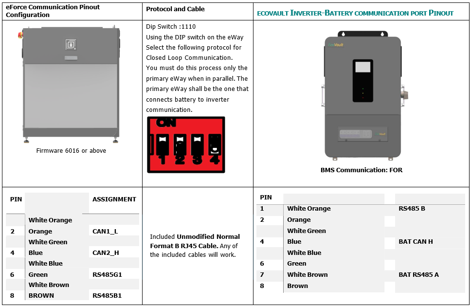
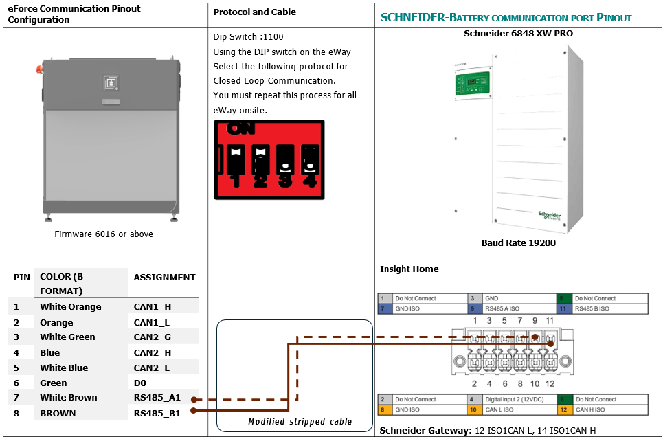
To ensure Closed Loop communication, please follow the process below. If making a communication cable, refer to the pin out diagram for an RJ45 cable below. Type B format ethernet cable may also be used.
Commissioning
1. Turn on the Inverter Battery Breaker on the Inverter
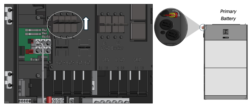 2. Turn ON the Disconnect on the
eWay. For paralleled battery systems, only turn
on the Primary Battery
2. Turn ON the Disconnect on the
eWay. For paralleled battery systems, only turn
on the Primary Battery
1. Turn on the Inverter Battery Breaker on the Inverter
2. Turn ON the Disconnect on the
eWay. For paralleled battery systems, only turn
on the Primary Battery
Programming the Inverter
Fortress Power Envy
Before setting the parameters, make sure the system is in Standby. Make sure to press
SET for each setup. Confirm the battery is doing Closed Loop Communications with the inverter
under the Battery of
the Data Section.
Battery Setup:
Self-Consumption Mode:
Back up:
Off-Grid:
Time of Use:
Sol-Ark:
Share Sol-Ark Monitoring w/Fortress
Set up Wi-Fi with Sol-Ark Inverter
using Sol-Ark’s My Sol-Ark App and have your site name and Wi-Fi dongle serial
number handy to register the system online
with Sol-Ark. After registering, use a laptop
to log into MySolArk via a web browser at http://mysolark.com
Note: For certain circumstances, temporarily use the batteries in open-loop communication mode, please
follow the
following link for open-loop settings:
1. To program the inverter
using the Sol-Ark inverter screen, go to battery setup menu:
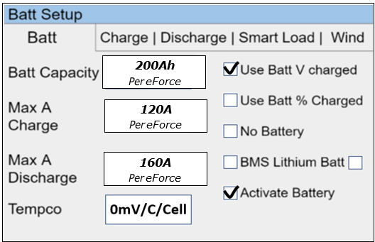
2. Program the 'Batt' tab first. Enter the settings as shown below and tap on 'OK' in the bottom of the menu afterwards
Closed Loop Settings:
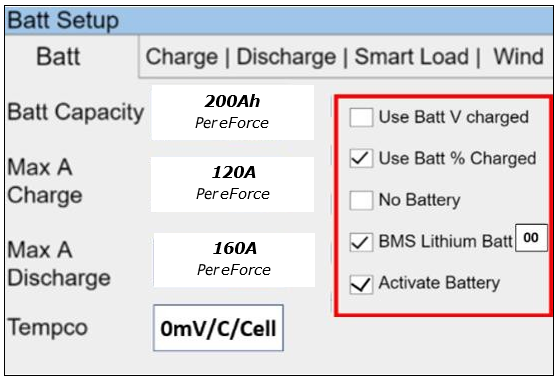
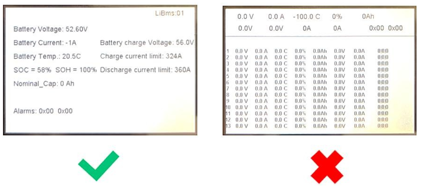
Confirm closed loop communication was established by going to the Home screen and selecting Li-BATT INFO
 Open Loop Settings:
Note:
a) If closed
loop communication is set up correctly, enabling
'BMS Lithium Batt 00' will
adjust some values automatically. In this tab, those would be 'Batt Capacity' and 'Tempco'.b) If the total charge/discharge current capacity of the batteries exceeds the inverter's capabilities, use the maximum current settings of the inverter.For example, if you have four eForce batteries and one Sol-Ark 12K inverter, based on the size of the battery bank, 'Max A Charge'
and ‘Max A discharge' should be 240A each. But Sol-Ark 12K can only carry 185A DC
going to or coming from the battery.
So, in this case, both 'Max A Charge' and 'Max A Discharge' would be set to 185A.c) If recovering a deeply discharged battery, adjust the above charge amps to 10A.
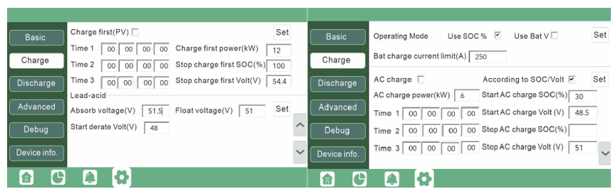
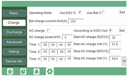
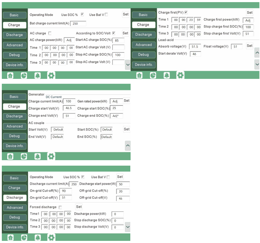
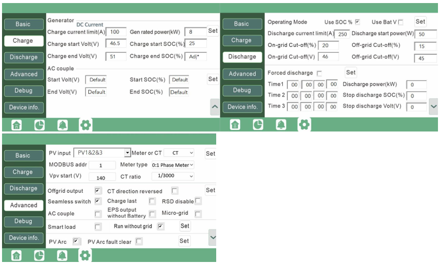
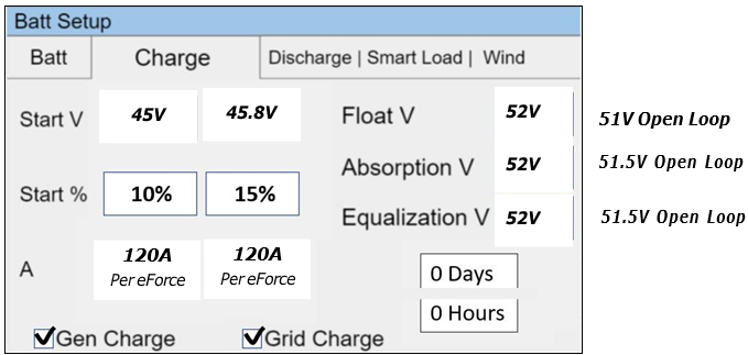
3. Next, program
the 'Charge' tab in the 'Battery Setup'
menu:
Note:
a) The settings shown in the latter screenshot are the most conventional ones, hence, adjustments may be required (please see the table below).The approach described in the note "2b" applies while programing this tab as well. Additionally, current set point (A) must not exceed generators' capability.
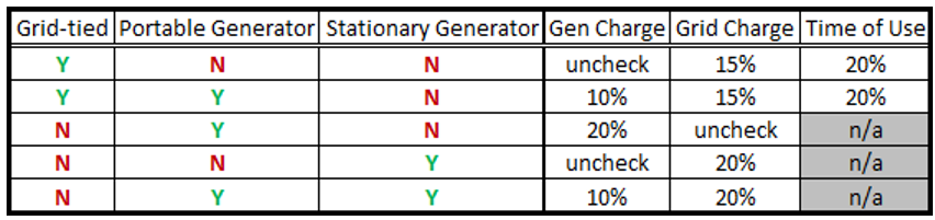 b) Larger generators are commonly tied into the grid side of the inverter rather than the dedicated generator input. Make check-marks and current adjustments accordingly. This fact was kept in mind while creating the last two rows of the table above.c) Fortress batteries may be discharged to its full rated capacity without voiding the warranty, but for best overall experience and battery life, limit the discharge to 80% except for very rare occasions. Here is a list of our suggested triggers:d) It is acceptable to raise the grid or generator start triggers to increase the reserve capacity of the system.
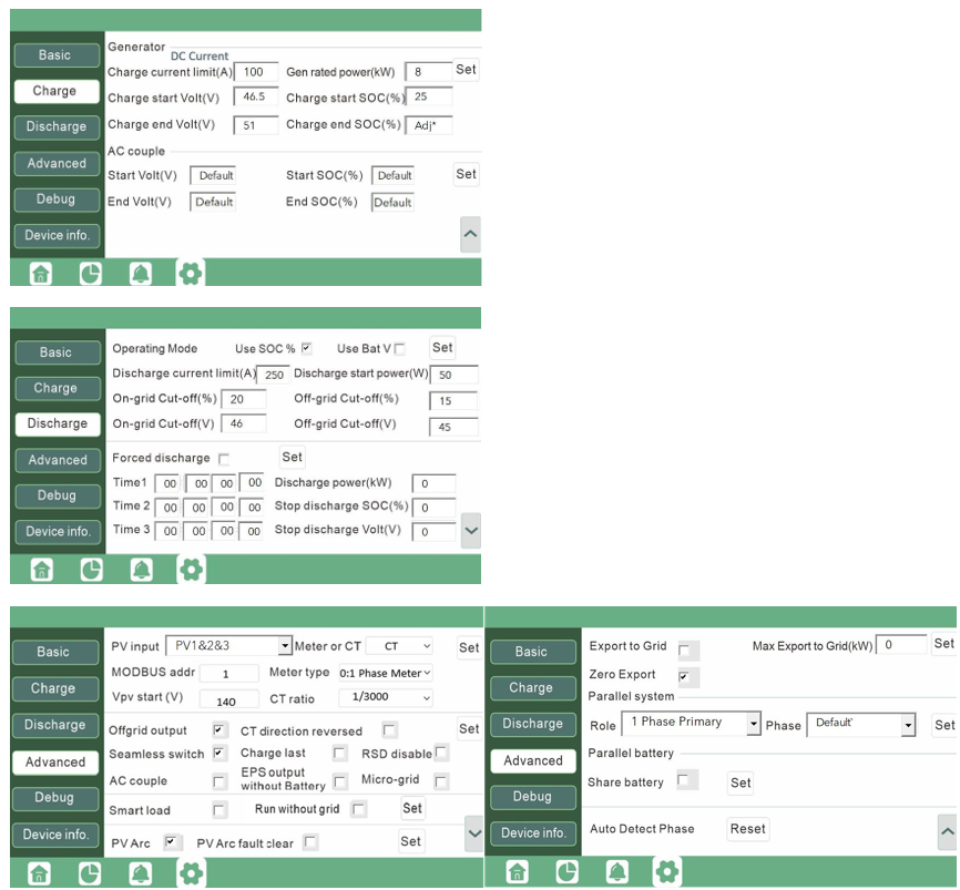
4. Program the Discharge tab:
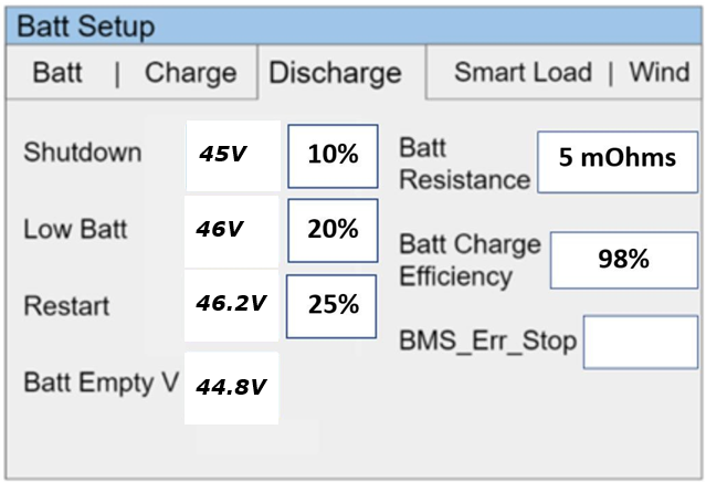
Note:
a) At 'Shutdown' state of charge (battery bank charge percentage), inverter prevents battery from powering the loads. The battery(s) will renew/continue providing power to the loads when the battery bank is recharged to 'Restart' state of charge. 'Shutdown' and 'Restart' state of charge set-points can be increased to increase the "reserve capacity" of the system, but that will cause less battery charge usage. The correct shutdown level is specific to the project site.
b) Low battery is an alarm also specific to the project site, integrated with the Sol-Ark monitoring app. We suggest a 20% state of charge as a low battery alarm level. But it is a good idea to increase it if the 'Shutdown' and 'Restart' set- points are increased.c) The battery empty voltage should not be lower than 44.8V. The last statement from the previous note applies to the 'Batt Empty V'. Usually this set-point does not exceed 45.5V.
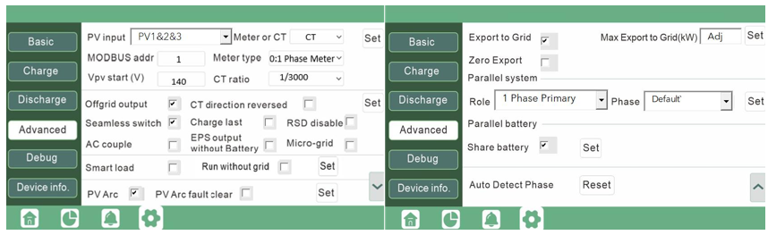
Grid Setup / Time-of-UseTime-of-use settings are specific to each end user but also important to having system behavior meeting customer expectations. system to behave as the end user wants it to behave. There are a few important things to know when programming Sol-Ark's time-of-use settings:1) Checking the "charge" column boxes will force a grid charge to that battery.2) Leaving the "charge" column boxes unchecked will act as a low battery cut-off.3) Enabling "grid-sell" will allow the battery to sell back to the grid when it is otherwise 100% full.4) Solar will charge the battery to 100% if there is enough sunlight available and all the loads are otherwise met.5) Additional settings worth exploring in the Grid Setup Menu are the frequency ranges and grid profile settings useful for generator compatibility.Back-up Only Customers:Batteries work better and last longer if they are used, rather than staying 100% full. Our recommendation is to allow the battery to drop to 70% during the early morning hours and then have it go to 100% during the day. You do not need to enable a grid-charge for this functionality. You may want to increase the grid start % or voltage in the battery setup menu. Time-of-use Customers:1) To maintain solar tax credit compliance, you will want to prioritize battery charging in the hours before the time-of- use period so that the battery is 100% going into the time frame.2) You may also want to enable a grid charge the hour before the time-of-use period to ensure the battery reaches 100%3) You may not want to discharge the battery too aggressively. Sticking to no more than 9kW per eVault or 3.3kW per eFlex Max is optimal for maximizing battery life under time-of-use grid sell-back. Likewise, selling back at less than the full rated value of the inverter is healthy for inverter life. So for example, if you can identify that the battery and inverter will be fully utilized over the time of use rate period by discharging at 5kW rate instead of the full rated capacity of the inverter, it will extend battery life.4) That said, the mantra is "use it or lose it" - it is more economically advantageous for the end user to use the battery when it is financially advantageous to do so, rather than to keep the battery at 100% always.
Bad Utility Buyback Rates aka "no net-metering" aka "bad net-metering":Allow the battery to discharge to a 20% state-of-charge over night, so that it can absorb as much solar power as possible during the day rather than having that energy sold back to the grid. Staggering the step down percentages throughout the night so that the battery so that the battery hits 20% right in the early morning will mitigate the risk of power outage between sun up and sun down. Maintain the final 20% time-of-use step with a grid charge to make sure the battery does not go below 20% (which would trigger a full grid recharge at 15% per prior steps). During the day, it does not matter if you prioritize the grid or the battery first when recharging with solar power.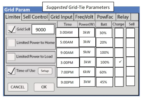
Note: Change the programming from Percentage to Voltage in the Battery setup menu. (Use Batt % Charge / Use Batt V charge)Here are more aggressive settings for minimizing sell-back to the grid (but allowing grid-sellback when the batteries are full).
Ecovault:
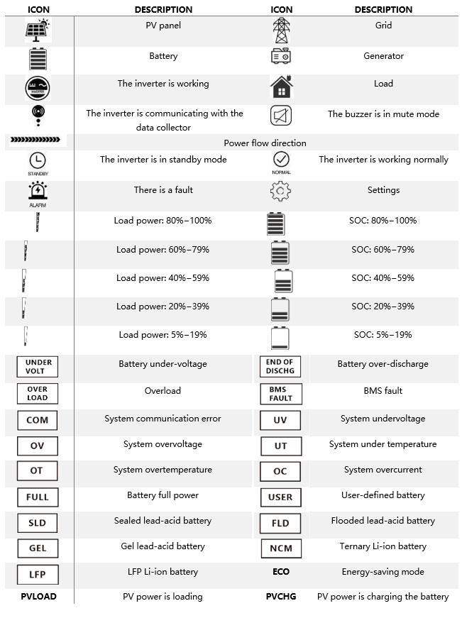
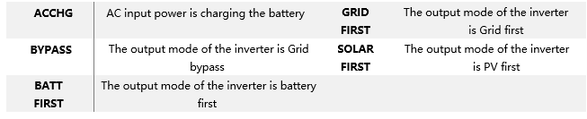
Operation and Display Panel
The operation and display panel of the inverter includes one LCD screen, three indicators, and four physical buttons.
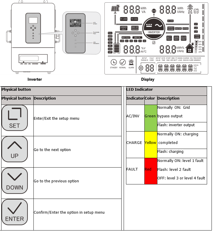
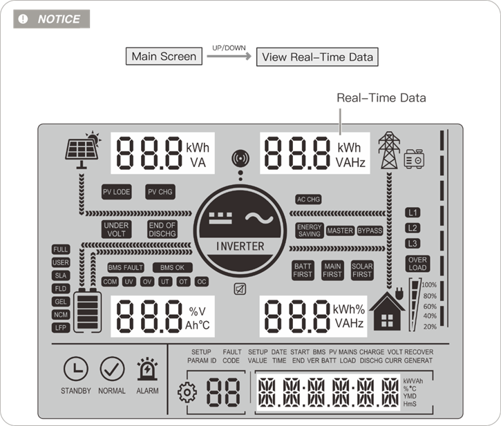
Real-time parameters view:
On the screen, press the UP/DOWN button to view real-time data of the inverter in operation
PAGE PV BATTERY AC INPUT LOAD GENERAL 1 PV input voltage Battery voltage Grid input voltage Single-phase voltage Current time 2 PV input current Battery current Grid input current Single-phase current Current date 3 PV input power Battery voltage Grid total input power Single-phase active power PV gross generation 4 PV generation of the day Battery current Grid charging capacity of the day Single-phase apparent power Total load consumption 5 PV heat sink temperature Heat sink temperature Grid frequency Inverter output frequency RS485 address 6 Rated open circuit voltage Rated battery voltage Bus voltage Rated output frequency Software version 7 Maximum PV charge current Maximum battery charges current Maximum grid charge current Total output active power / 8
/ Total output apparent frequency /
Settings: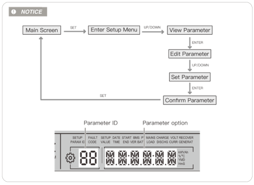 Notice:
If you use lithium battery which has communication with Inverter, please skip all Battery Voltage setting (04~07)
INVERTER MODE OF OPERATION DESCRIPTION00 Exit ESC Exit the setup Menu 01 ESS UTI (default) Backup Mode (Load Source Priority: PV → Grid → Battery)
Operation mode Backup Mode
If PV power is insufficient, the system uses both PV and grid power to support the load.
When PV power exceeds the demand, the excess energy charges the battery.
Grid power is only used for charging when the battery is over-discharged (if setting 06 is PV-only charging, the grid will not charge the battery).
The battery discharges only in off-grid mode
SBU Self-Consumption Mode (Load Source Priority: PV → Battery → Grid)
Self-Consumption
Mode (Recommend) PV Power Priority – The system first uses solar (PV) power to supply the load.
Battery Backup – If PV power is insufficient, the system draws power from the battery to support the load.
Grid as Last Resort – The system switches to grid power only when the battery voltage drops below the set threshold (Parameter ④).
Return to PV/Battery – Once the battery voltage recovers above the set threshold (Parameter ⑤), the system switches back to PV or battery power for load supply.
SOL Self-Consumption Mode (Load Source Priority: PV → Battery → Grid)
The PV mode is to be applied first and when the PV power is unavailable or the battery voltage is lower than the set value in the item 4, it will switch to the Grid mode
SUB PV and Grid prioritize Charging the Battery
Battery
Charging Priority Mode PV Priority for Charging – The system prioritizes PV power to charge the battery.
Grid-Assisted Charging – If PV power is insufficient, the system uses both PV and grid power for charging (except when Parameter 06 is set to PV- only charging, in which case the grid will not charge the battery).
Grid Powers the Load – While the battery is charging, the grid supplies power to the load when PV alone is not sufficient.
Hybrid Load Supply – If PV power is enough for charging but insufficient for the load, the system will use both PV and grid power to support the load.
Battery Discharges Only in Off-Grid Mode – The battery does not discharge when the system is connected to the grid; it is reserved for off- grid operation only.
Set up Wi-Fi with Sol-Ark Inverter using Sol-Ark’s My Sol-Ark App and have your site name and Wi-Fi dongle serial number handy to register the system online with Sol-Ark. After registering, use a laptop to log into MySolArk via a web browser at http://mysolark.com
Confirm closed loop communication was established by going to the Home screen and selecting Li-BATT INFO
Open Loop Settings:
Note:
a) If closed loop communication is set up correctly, enabling 'BMS Lithium Batt 00' will adjust some values automatically. In this tab, those would be 'Batt Capacity' and 'Tempco'.
b) If the total charge/discharge current capacity of the batteries exceeds the inverter's capabilities, use the maximum current settings of the inverter.
For example, if you have four eForce batteries and one Sol-Ark 12K inverter, based on the size of the battery bank, 'Max A Charge'
and ‘Max A discharge' should be 240A each. But Sol-Ark 12K can only carry 185A DC
going to or coming from the battery.
So, in this case, both 'Max A Charge' and 'Max A Discharge' would be set to 185A.
c) If recovering a deeply discharged battery, adjust the above charge amps to 10A.
3. Next, program
the 'Charge' tab in the 'Battery Setup'
menu:
Note:
a) The settings shown in the latter screenshot are the most conventional ones, hence, adjustments may be required (please see the table below).
The approach described in the note "2b" applies while programing this tab as well. Additionally, current set point (A) must not exceed generators' capability.
b) Larger generators are commonly tied into the grid side of the inverter rather than the dedicated generator input. Make check-marks and current adjustments accordingly. This fact was kept in mind while creating the last two rows of the table above.
c) Fortress batteries may be discharged to its full rated capacity without voiding the warranty, but for best overall experience and battery life, limit the discharge to 80% except for very rare occasions. Here is a list of our suggested triggers:
d) It is acceptable to raise the grid or generator start triggers to increase the reserve capacity of the system.
4. Program the Discharge tab:
Note:
a) At 'Shutdown' state of charge (battery bank charge percentage), inverter prevents battery from powering the loads. The battery(s) will renew/continue providing power to the loads when the battery bank is recharged to 'Restart' state of charge. 'Shutdown' and 'Restart' state of charge set-points can be increased to increase the "reserve capacity" of the system, but that will cause less battery charge usage. The correct shutdown level is specific to the project site.
b) Low battery is an alarm also specific to the project site, integrated with the Sol-Ark monitoring app. We suggest a 20% state of charge as a low battery alarm level. But it is a good idea to increase it if the 'Shutdown' and 'Restart' set- points are increased.
c) The battery empty voltage should not be lower than 44.8V. The last statement from the previous note applies to the 'Batt Empty V'. Usually this set-point does not exceed 45.5V.
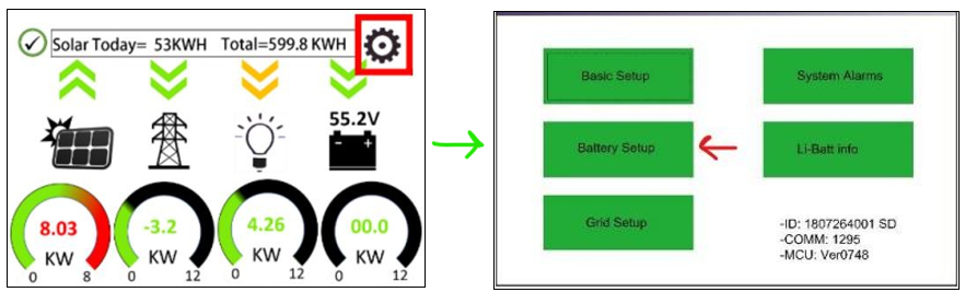
Grid Setup / Time-of-Use
Time-of-use settings are specific to each end user but also important to having system behavior meeting customer expectations. system to behave as the end user wants it to behave. There are a few important things to know when programming Sol-Ark's time-of-use settings:
1) Checking the "charge" column boxes will force a grid charge to that battery.
2) Leaving the "charge" column boxes unchecked will act as a low battery cut-off.
3) Enabling "grid-sell" will allow the battery to sell back to the grid when it is otherwise 100% full.
4) Solar will charge the battery to 100% if there is enough sunlight available and all the loads are otherwise met.
5) Additional settings worth exploring in the Grid Setup Menu are the frequency ranges and grid profile settings useful for generator compatibility.
Back-up Only Customers:
Batteries work better and last longer if they are used, rather than staying 100% full. Our recommendation is to allow the battery to drop to 70% during the early morning hours and then have it go to 100% during the day. You do not need to enable a grid-charge for this functionality. You may want to increase the grid start % or voltage in the battery setup menu.
Time-of-use Customers:
1) To maintain solar tax credit compliance, you will want to prioritize battery charging in the hours before the time-of- use period so that the battery is 100% going into the time frame.
2) You may also want to enable a grid charge the hour before the time-of-use period to ensure the battery reaches 100%
3) You may not want to discharge the battery too aggressively. Sticking to no more than 9kW per eVault or 3.3kW per eFlex Max is optimal for maximizing battery life under time-of-use grid sell-back. Likewise, selling back at less than the full rated value of the inverter is healthy for inverter life. So for example, if you can identify that the battery and inverter will be fully utilized over the time of use rate period by discharging at 5kW rate instead of the full rated capacity of the inverter, it will extend battery life.
4) That said, the mantra is "use it or lose it" - it is more economically advantageous for the end user to use the battery when it is financially advantageous to do so, rather than to keep the battery at 100% always.
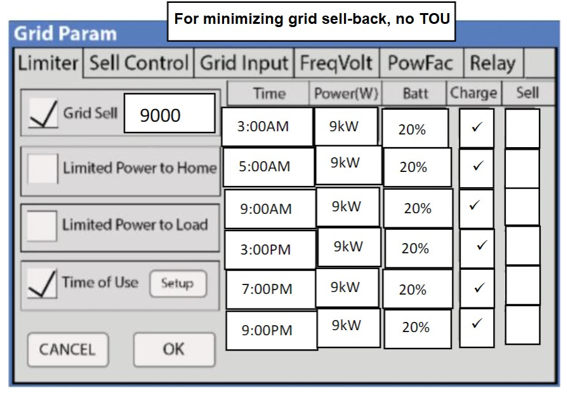
Bad Utility Buyback Rates aka "no net-metering" aka "bad net-metering":
Allow the battery to discharge to a 20% state-of-charge over night, so that it can absorb as much solar power as possible during the day rather than having that energy sold back to the grid. Staggering the step down percentages throughout the night so that the battery so that the battery hits 20% right in the early morning will mitigate the risk of power outage between sun up and sun down. Maintain the final 20% time-of-use step with a grid charge to make sure the battery does not go below 20% (which would trigger a full grid recharge at 15% per prior steps). During the day, it does not matter if you prioritize the grid or the battery first when recharging with solar power.
Note: Change the programming from Percentage to Voltage in the Battery setup menu. (Use Batt % Charge / Use Batt V charge)
Here are more aggressive settings for minimizing sell-back to the grid (but allowing grid-sellback when the batteries are full).
Ecovault:
Operation and Display Panel
The operation and display panel of the inverter includes one LCD screen, three indicators, and four physical buttons.
Real-time parameters view:
On the screen, press the UP/DOWN button to view real-time data of the inverter in operation
PAGE | PV | BATTERY | AC INPUT | LOAD | GENERAL |
1 | PV input voltage | Battery voltage | Grid input voltage | Single-phase voltage | Current time |
| 2 | PV input current | Battery current | Grid input current | Single-phase current | Current date |
3 | PV input power | Battery voltage | Grid total input power | Single-phase active power | PV gross generation |
4 | PV generation of the day | Battery current | Grid charging capacity of the day | Single-phase apparent power | Total load consumption |
5 | PV heat sink temperature | Heat sink temperature | Grid frequency | Inverter output frequency | RS485 address |
6 | Rated open circuit voltage | Rated battery voltage | Bus voltage | Rated output frequency | Software version |
7 | Maximum PV charge current | Maximum battery charges current | Maximum grid charge current | Total output active power | / |
8 | / | Total output apparent frequency | / |
Settings:
Notice:
If you use lithium battery which has communication with Inverter, please skip all Battery Voltage setting (04~07)
INVERTER MODE OF OPERATION DESCRIPTION
00 | Exit | ESC | Exit the setup Menu |
01 | ESS | UTI (default) | Backup Mode (Load Source Priority: PV → Grid → Battery) |
Operation mode | Backup Mode | ||
If PV power is insufficient, the system uses both PV and grid power to support the load. | |||
When PV power exceeds the demand, the excess energy charges the battery. | |||
Grid power is only used for charging when the battery is over-discharged (if setting 06 is PV-only charging, the grid will not charge the battery). | |||
The battery discharges only in off-grid mode | |||
SBU | Self-Consumption Mode (Load Source Priority: PV → Battery → Grid) | ||
Self-Consumption | |||
Mode (Recommend) | PV Power Priority – The system first uses solar (PV) power to supply the load. | ||
Battery Backup – If PV power is insufficient, the system draws power from the battery to support the load. | |||
Grid as Last Resort – The system switches to grid power only when the battery voltage drops below the set threshold (Parameter ④). | |||
Return to PV/Battery – Once the battery voltage recovers above the set threshold (Parameter ⑤), the system switches back to PV or battery power for load supply. | |||
SOL | Self-Consumption Mode (Load Source Priority: PV → Battery → Grid) The PV mode is to be applied first and when the PV power is unavailable or the battery voltage is lower than the set value in the item 4, it will switch to the Grid mode | ||
| SUB | PV and Grid prioritize Charging the Battery | ||
Battery | |||
Charging Priority Mode | PV Priority for Charging – The system prioritizes PV power to charge the battery. | ||
Grid-Assisted Charging – If PV power is insufficient, the system uses both PV and grid power for charging (except when Parameter 06 is set to PV- only charging, in which case the grid will not charge the battery). | |||
Grid Powers the Load – While the battery is charging, the grid supplies power to the load when PV alone is not sufficient. | |||
Hybrid Load Supply – If PV power is enough for charging but insufficient for the load, the system will use both PV and grid power to support the load. | |||
Battery Discharges Only in Off-Grid Mode – The battery does not discharge when the system is connected to the grid; it is reserved for off- grid operation only. |
FN PARAMETER EFORCE EFLEX MAX/EFLEX EVAULT MAX 04 Battery Low Cut of Voltage 48V 51.2V 51.2V
WHEN PARAMETER ITEM 01 IS SET TO SBU (SOLAR-BATTERY UTILITY) OR SOL (SOLAR ONLY) MODE, THE SYSTEM PRIORITIZES PV AND BATTERY POWER. HOWEVER, IF THE BATTERY VOLTAGE DROPS BELOW THE SET CUT-OFF POINT, THE POWER SOURCE AUTOMATICALLY SWITCHES FROM THE INVERTER TO THE GRID TO PREVENT BATTERY OVER-DISCHARGE06 Grid Charge Setting SNU (RECOMMENDED) SNU (RECOMMENDED) SNU (RECOMMENDED)
SNU (DEFAULT): BOTH PV AND GRID CAN CHARGE THE BATTERY, WITH PV AS THE PRIORITY CHARGING SOURCE OSO: GRID POWER WILL NOT CHARGE BATTERY07 Battery Charge Current 120Adc per eForce 60Adc per eFlex MAX/eFlex 140Adc per eVault MAX 08 Battery Type L14/15/16 L14/15/16 L14/15/16 09 Battery boost charge voltage (Bulk & Absorption) 51.4V 55.2V 55.2V 10 60min 60min 60min 60min 11 Battery floating charge voltage 51V 54v 54V 12 Battery over- discharge Protection voltage (delayed shutdown) 44.8V 48V 48V 13 50s 50s 50s 50s
WHEN THE BATTERY VOLTAGE DROPS BELOW THE THRESHOLD SET IN PARAMETER ITEM 12, THE INVERTER WILL WAIT FOR THE DELAY TIME SET IN THIS PARAMETER BEFORE SHUTTING OFF THE OUTPUT.
SETTING RANGE: 5S – 50SADJUSTMENT STEP: 5S
PURPOSE: THIS DELAY PREVENTS UNNECESSARY SHUTDOWNS DUE TO TEMPORARY VOLTAGE DIPS, ENSURING STABLE SYSTEM OPERATION WHILE STILL PROTECTING THE BATTERY FROM OVER DISCHARGE
14 Battery under- voltage alarm threshold 46 51.2 51.2
WHEN THE BATTERY VOLTAGE IS LOWER THAN THE THRESHOLD, IT WILL GIVE AN UNDER-VOLTAGE ALARM AND THE OUTPUT WILL NOT SHUT DOWN. SETTING RANGE: 40 V−52 V, WITH A STEP OF 0.4 V
15 Battery over discharge protection voltage 44.8 48 48 16 Battery equalization charge DIS (Default) DIS (Default) DIS (Default)
DIS: DISABLE EQUALIZATION CHARGE
ENA: ENABLE EQUALIZATION CHARGE, ONLY AVAILABLE FOR FLOODED LEAD-ACID BATTERIES, SEALED LEAD-ACID BATTERIES, AND USER-DEFINED ONES
32 RS485 Communication Function CAN CAN CAN 33 BMS Communication FOR FOR FOR 35 Battery under- voltage recovery threshold 46 51.2 51.2 37 Battery Recharge Voltage 48 51.2 51.2 39 Charge current limit (Communicate with BMS)
LCBMS (default) LCBMS (default) LCBMS (default)
LCSET: THE MAXIMUM BATTERY CHARGE CURRENT IS NOT GREATER THAN THE SET VALUE OF “07”LCBMS (DEFAULT): THE MAXIMUM BATTERY CHARGE CURRENT IS NOT GREATER THAN THE MAXIMUM BMS ALLOWED CURRENTLCINV: THE MAXIMUM BATTERY CHARGE CURRENT IS NOT GREATER THAN INVERTER ALLOWED CURRENT
40-45 Start and End Charge time 1,2,3 00:00:00 00:00:00 00:00:00 46 Timed battery charge function DIS DIS DIS
DIS (DEFAULT): DISABLE THE FUNCTIONENA: WHEN THE TIMED GRID CHARGING/LOAD SUPPLY FUNCTION IS ENABLED, THE POWER SUPPLY MODE WILL OPERATE BASED ON THE CONFIGURED TIME PARAMETERS AND BATTERY STATE (RANGE 0:00:00−23:59:00)
1. OPERATING MODES SBU MODE ACTIVATION:
THE SYSTEM WILL OPERATE IN SBU MODE WHEN TIMED GRID CHARGING IS ENABLED. THE INVERTER WILL PRIORITIZE SOLAR (S) AND BATTERY (B) POWER, SUPPLYING LOADS FROM THESE SOURCES. WHEN THE SYSTEM REACHES THE CONFIGURED CHARGING PERIOD OR THE BATTERY ENTERS AN OVER-DISCHARGE STATE, IT WILL SWITCH TO GRID (U) POWER FOR BATTERY CHARGING.
UTI MODE ACTIVATION (WITH TIMED DISCHARGE ENABLED): IF THE TIMED DISCHARGE FUNCTION IS ALSO ENABLED, THE SYSTEM WILL SWITCH TO UTI MODE. IN THIS MODE, THE INVERTER: USES GRID POWER FOR BATTERY CHARGING ONLY DURING THE SET CHARGING PERIOD. SWITCHES TO BATTERY INVERTER OPERATION DURING THE CONFIGURED DISCHARGE PERIOD OR IF THE GRID POWER IS LOST.
47-52 Start and End discharge time 1,2,3 00:00:00 00:00:00 00:00:00 53 Timed battery discharge function DIS DIS DIS
DIS (DEFAULT): DISABLE THE FUNCTION
ENA: AFTER THE TIMED BATTERY DISCHARGE FUNCTION IS ENABLED, THE POWER SUPPLY MODE WILL BE CHANGED INTO UTI, WHERE THE SYSTEM ONLY SWITCHES TO THE POWER SUPPLY OF BATTERY INVERTER DURING THE SET DISCHARGE PERIOD OR GRID FAILURE
58 SOC setting for discharge alarming 25% 25% 25%
WHEN THE CAPACITY IS LESS THAN THE SET VALUE, THE SOC ALARMS (UNIT: %, ONLY AVAILABLE DURING NORMAL BMS COMMUNICATION)
59 SOC setting for discharge cutoff 20% 20% 20%
WHEN THE CAPACITY IS LESS THAN THE SET VALUE, THE DISCHARGE STOPS (UNIT: %, ONLY AVAILABLE DURING
NORMAL
BMS COMMUNICATION)
60 SOC setting for charge cutoff 100% 100% 100%
WHEN THE CAPACITY IS GREATER THAN THE SET VALUE, THE CHARGE STOPS (UNIT: %, ONLY VALID DURING NORMAL BMS COMMUNICATION)
61 SOC setting for switching to grid 25% 25% 25%
WHEN THE CAPACITY IS LESS THAN THE SET VALUE, IT SWITCHES TO GRID (UNIT: %, ONLY AVAILABLE DURING NORMAL BMS COMMUNICATION)
62 SOC setting for Switching to inverter Output 100
100
WHEN THE CAPACITY IS GREATER THAN THE SET VALUE, IT SWITCHES TO THE INVERTER OUTPUT MODE (UNIT: %, ONLY AVAILABLE DURING NORMAL BMS COMMUNICATION)
73 Max charging current by generator 80Adc 80Adc 80Adc
SCHNEIDER:
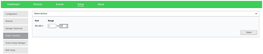
1. Connect to Schneider’s Insight Local2. Go to SETUP>CONFIGURATION>MODBUS SETTINGS and select 19200 Baud Rate. Click Apply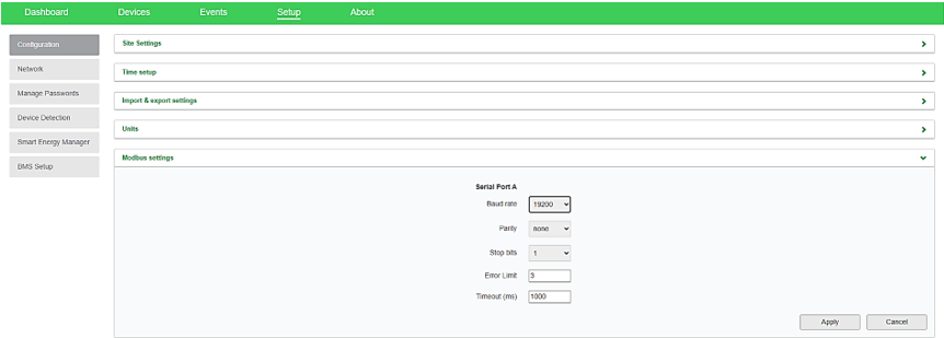 3. Go to SETUP>Device Detection> input range 1-10. Click Detect.
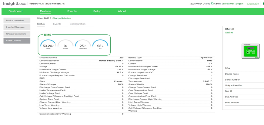
 4. Make sure that Insight Home is reading the battery internal parameters
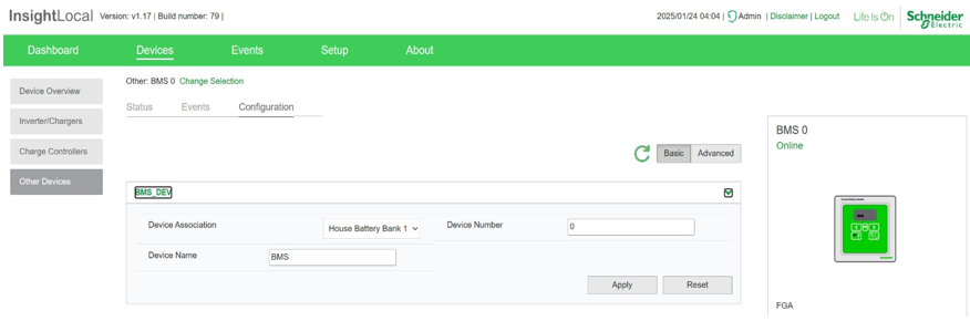
 5. Associate Battery as House Battery Bank 1
 Parameter Settings
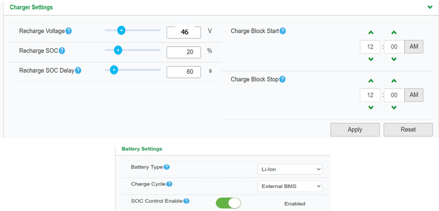
PARAMETER VALUECHARGER SETTINGS
RECHARGE VOLTAGE 46V RECHARGE SOC 20% RECHARGE SOC 60s
BATTERY SETTINGS
BATTERY TYPE LI-ION CHARGE CYCLE EXTERNAL BMS SOC CONTROL ENABLE ENABLED BATTERY BANK CAPACITY 200aH per eForce MAXIMUM CHARGE RATE 100% MAXIMUM BULK CHARGE CURRENT 120A per eForce MAXIMUM ABSORPTION CHARGE CURRENT 120A per eForce MAXIMUM FLOAR CHARGE 120A per eForce DEFAULT BATTERY TEMPERATURE WARM ABSORPTION TIME 3600 BULK/BOOST VOLTAGE 51.5 ABSORPTION VOLTAGE SET POINT 51.5 MAXIMUM DISCHARGE CURRENT 160A per eForce MAXIMUM DISCHARGE TIME INTERVAL 8 LOW BATTERY CUT OUT 44.8V LOW BATTERY CUT OUT DELAY 10s LOW BATTERY CUT OUT HYSTERESIS 2 LOW BATTERY CUTOUT WARNING OFFSET 2 HIGH BATTERY CUT OUT 58V CHARGE CYCLE TIMEOUT 1440s HIGH SOC CUT OUT 99% HIGH SOC CUT OUT DELAY 2s LOW SOC CUT OUT 15% LOW SOC CUT OUT DELAY 60s
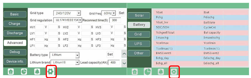
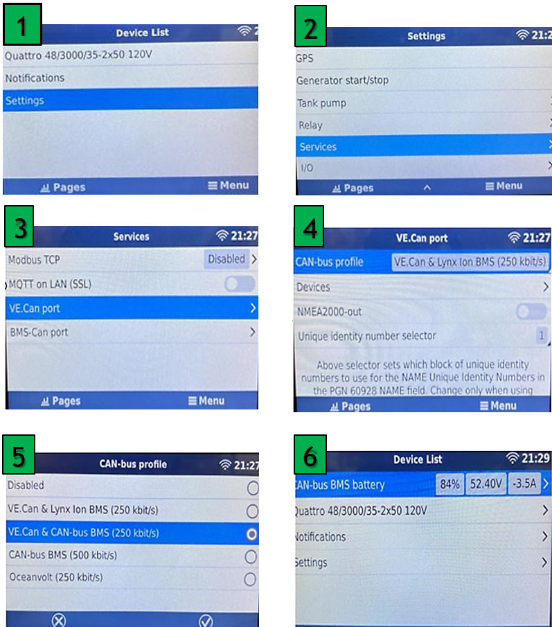
VICTRON:
Setup Steps
FN | PARAMETER | EFORCE | EFLEX MAX/EFLEX | EVAULT MAX |
04 | Battery Low Cut of Voltage | 48V | 51.2V | 51.2V |
WHEN PARAMETER ITEM 01 IS SET TO SBU (SOLAR-BATTERY UTILITY) OR SOL (SOLAR ONLY) MODE, THE SYSTEM PRIORITIZES PV AND BATTERY POWER. HOWEVER, IF THE BATTERY VOLTAGE DROPS BELOW THE SET CUT-OFF POINT, THE POWER SOURCE AUTOMATICALLY SWITCHES FROM THE INVERTER TO THE GRID TO PREVENT BATTERY OVER-DISCHARGE
06 | Grid Charge Setting | SNU (RECOMMENDED) | SNU (RECOMMENDED) | SNU (RECOMMENDED) |
SNU (DEFAULT): BOTH PV AND GRID CAN CHARGE THE BATTERY, WITH PV AS THE PRIORITY CHARGING SOURCE OSO: GRID POWER WILL NOT CHARGE BATTERY
07 | Battery Charge Current | 120Adc per eForce | 60Adc per eFlex MAX/eFlex | 140Adc per eVault MAX |
08 | Battery Type | L14/15/16 | L14/15/16 | L14/15/16 |
09 | Battery boost charge voltage (Bulk & Absorption) | 51.4V | 55.2V | 55.2V |
10 | 60min | 60min | 60min | 60min |
11 | Battery floating charge voltage | 51V | 54v | 54V |
12 | Battery over- discharge Protection voltage (delayed shutdown) | 44.8V | 48V | 48V |
13 | 50s | 50s | 50s | 50s |
WHEN THE BATTERY VOLTAGE DROPS BELOW THE THRESHOLD SET IN PARAMETER ITEM 12, THE INVERTER WILL WAIT FOR THE DELAY TIME SET IN THIS PARAMETER BEFORE SHUTTING OFF THE OUTPUT.
SETTING RANGE: 5S – 50S
ADJUSTMENT STEP: 5S
PURPOSE: THIS DELAY PREVENTS UNNECESSARY SHUTDOWNS DUE TO TEMPORARY VOLTAGE DIPS, ENSURING STABLE SYSTEM OPERATION WHILE STILL PROTECTING THE BATTERY FROM OVER DISCHARGE
14 | Battery under- voltage alarm threshold | 46 | 51.2 | 51.2 |
WHEN THE BATTERY VOLTAGE IS LOWER THAN THE THRESHOLD, IT WILL GIVE AN UNDER-VOLTAGE ALARM AND THE OUTPUT WILL NOT SHUT DOWN. SETTING RANGE: 40 V−52 V, WITH A STEP OF 0.4 V
15 | Battery over discharge protection voltage | 44.8 | 48 | 48 |
16 | Battery equalization charge | DIS (Default) | DIS (Default) | DIS (Default) |
DIS: DISABLE EQUALIZATION CHARGE
ENA: ENABLE EQUALIZATION CHARGE, ONLY AVAILABLE FOR FLOODED LEAD-ACID BATTERIES, SEALED LEAD-ACID BATTERIES, AND USER-DEFINED ONES
32 | RS485 Communication Function | CAN | CAN | CAN |
33 | BMS Communication | FOR | FOR | FOR |
35 | Battery under- voltage recovery threshold | 46 | 51.2 | 51.2 |
37 | Battery Recharge Voltage | 48 | 51.2 | 51.2 |
39 | Charge current limit (Communicate with BMS) | LCBMS (default) | LCBMS (default) | LCBMS (default) |
LCSET: THE MAXIMUM BATTERY CHARGE CURRENT IS NOT GREATER THAN THE SET VALUE OF “07”
LCBMS (DEFAULT): THE MAXIMUM BATTERY CHARGE CURRENT IS NOT GREATER THAN THE MAXIMUM BMS ALLOWED CURRENT
LCINV: THE MAXIMUM BATTERY CHARGE CURRENT IS NOT GREATER THAN INVERTER ALLOWED CURRENT
40-45 | Start and End Charge time 1,2,3 | 00:00:00 | 00:00:00 | 00:00:00 |
46 | Timed battery charge function | DIS | DIS | DIS |
DIS (DEFAULT): DISABLE THE FUNCTION
ENA: WHEN THE TIMED GRID CHARGING/LOAD SUPPLY FUNCTION IS ENABLED, THE POWER SUPPLY MODE WILL OPERATE BASED ON THE CONFIGURED TIME PARAMETERS AND BATTERY STATE (RANGE 0:00:00−23:59:00)
1. OPERATING MODES SBU MODE ACTIVATION:
THE SYSTEM WILL OPERATE IN SBU MODE WHEN TIMED GRID CHARGING IS ENABLED. THE INVERTER WILL PRIORITIZE SOLAR (S) AND BATTERY (B) POWER, SUPPLYING LOADS FROM THESE SOURCES. WHEN THE SYSTEM REACHES THE CONFIGURED CHARGING PERIOD OR THE BATTERY ENTERS AN OVER-DISCHARGE STATE, IT WILL SWITCH TO GRID (U) POWER FOR BATTERY CHARGING.
UTI MODE ACTIVATION (WITH TIMED DISCHARGE ENABLED): IF THE TIMED DISCHARGE FUNCTION IS ALSO ENABLED, THE SYSTEM WILL SWITCH TO UTI MODE. IN THIS MODE, THE INVERTER: USES GRID POWER FOR BATTERY CHARGING ONLY DURING THE SET CHARGING PERIOD. SWITCHES TO BATTERY INVERTER OPERATION DURING THE CONFIGURED DISCHARGE PERIOD OR IF THE GRID POWER IS LOST.
47-52 | Start and End discharge time 1,2,3 | 00:00:00 | 00:00:00 | 00:00:00 |
53 | Timed battery discharge function | DIS | DIS | DIS |
DIS (DEFAULT): DISABLE THE FUNCTION
ENA: AFTER THE TIMED BATTERY DISCHARGE FUNCTION IS ENABLED, THE POWER SUPPLY MODE WILL BE CHANGED INTO UTI, WHERE THE SYSTEM ONLY SWITCHES TO THE POWER SUPPLY OF BATTERY INVERTER DURING THE SET DISCHARGE PERIOD OR GRID FAILURE
58 | SOC setting for discharge alarming | 25% | 25% | 25% |
WHEN THE CAPACITY IS LESS THAN THE SET VALUE, THE SOC ALARMS (UNIT: %, ONLY AVAILABLE DURING NORMAL BMS COMMUNICATION)
| 59 | SOC setting for discharge cutoff | 20% | 20% | 20% |
WHEN THE CAPACITY IS LESS THAN THE SET VALUE, THE DISCHARGE STOPS (UNIT: %, ONLY AVAILABLE DURING
NORMAL
BMS COMMUNICATION)
| 60 | SOC setting for charge cutoff | 100% | 100% | 100% |
WHEN THE CAPACITY IS GREATER THAN THE SET VALUE, THE CHARGE STOPS (UNIT: %, ONLY VALID DURING NORMAL BMS COMMUNICATION)
| 61 | SOC setting for switching to grid | 25% | 25% | 25% |
WHEN THE CAPACITY IS LESS THAN THE SET VALUE, IT SWITCHES TO GRID (UNIT: %, ONLY AVAILABLE DURING NORMAL BMS COMMUNICATION)
| 62 | SOC setting for Switching to inverter Output | 100 | 100 |
WHEN THE CAPACITY IS GREATER THAN THE SET VALUE, IT SWITCHES TO THE INVERTER OUTPUT MODE (UNIT: %, ONLY AVAILABLE DURING NORMAL BMS COMMUNICATION)
| 73 | Max charging current by generator | 80Adc | 80Adc | 80Adc |
SCHNEIDER:
1. Connect to Schneider’s Insight Local
2. Go to SETUP>CONFIGURATION>MODBUS SETTINGS and select 19200 Baud Rate. Click Apply
3. Go to SETUP>Device Detection> input range 1-10. Click Detect.
4. Make sure that Insight Home is reading the battery internal parameters
5. Associate Battery as House Battery Bank 1
Parameter Settings
PARAMETER VALUE
CHARGER SETTINGS |
RECHARGE VOLTAGE | 46V |
| RECHARGE SOC | 20% |
RECHARGE SOC | 60s |
BATTERY SETTINGS |
BATTERY TYPE | LI-ION |
CHARGE CYCLE | EXTERNAL BMS |
SOC CONTROL ENABLE | ENABLED |
BATTERY BANK CAPACITY | 200aH per eForce |
MAXIMUM CHARGE RATE | 100% |
MAXIMUM BULK CHARGE CURRENT | 120A per eForce |
MAXIMUM ABSORPTION CHARGE CURRENT | 120A per eForce |
MAXIMUM FLOAR CHARGE | 120A per eForce |
DEFAULT BATTERY TEMPERATURE | WARM |
ABSORPTION TIME | 3600 |
BULK/BOOST VOLTAGE | 51.5 |
ABSORPTION VOLTAGE SET POINT | 51.5 |
MAXIMUM DISCHARGE CURRENT | 160A per eForce |
MAXIMUM DISCHARGE TIME INTERVAL | 8 |
LOW BATTERY CUT OUT | 44.8V |
LOW BATTERY CUT OUT DELAY | 10s |
LOW BATTERY CUT OUT HYSTERESIS | 2 |
LOW BATTERY CUTOUT WARNING OFFSET | 2 |
HIGH BATTERY CUT OUT | 58V |
CHARGE CYCLE TIMEOUT | 1440s |
HIGH SOC CUT OUT | 99% |
HIGH SOC CUT OUT DELAY | 2s |
LOW SOC CUT OUT | 15% |
LOW SOC CUT OUT DELAY | 60s |
VICTRON:
Setup Steps
Related Articles
eForce Installation Manual
1. Abbreviations 2. Change Log VERSION CHANGE DESCRIPTION EM-V1.0 EM-V1.2 1. Include Pinout definition EM-V1.3 2. Vertical installation with inverter instructions added EM-V1.4 1. Added dimensions for 2-3 battery vertical installation. 2. Changed ...eForce Wall-Mount Installation Manual
Safety and Precaution Instructions Mounting a heavy lithium battery to a wall requires careful planning and adherence to safety standards to prevent injury, equipment damage, or property hazards. Below are detailed instructions considering best ...