eForce Inverter Integration Guide (Schneider)
Important Notice
This Quick Guide does not exempt the installer or User from reading each product manual. Failure to do so may risk damaging both Fortress Power equipment and other manufacturers and void warranty.
Connection Diagrams
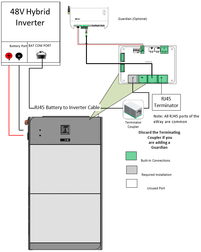
Connection Overview
Parallel Connection Overview
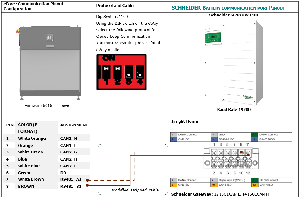
Closed loop and Pinout Definitions
To ensure Closed Loop communication, please follow the process below. If making a communication cable, refer to the pin out diagram for an RJ45 cable below. Type B format ethernet cable may also be used.
Important Notice
This Quick Guide does not exempt the installer or User from reading each product manual. Failure to do so may risk damaging both Fortress Power equipment and other manufacturers and void warranty.
Connection Diagrams
Connection Overview
Parallel Connection Overview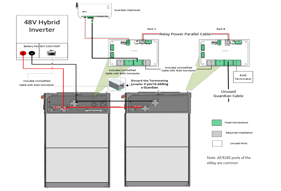
This Quick Guide does not exempt the installer or User from reading each product manual. Failure to do so may risk damaging both Fortress Power equipment and other manufacturers and void warranty.
Parallel Connection Overview
Closed loop and Pinout Definitions
To ensure Closed Loop communication, please follow the process below. If making a communication cable, refer to the pin out diagram for an RJ45 cable below. Type B format ethernet cable may also be used.
Commissioning
1. Turn on the Inverter Battery Breaker on the Inverter
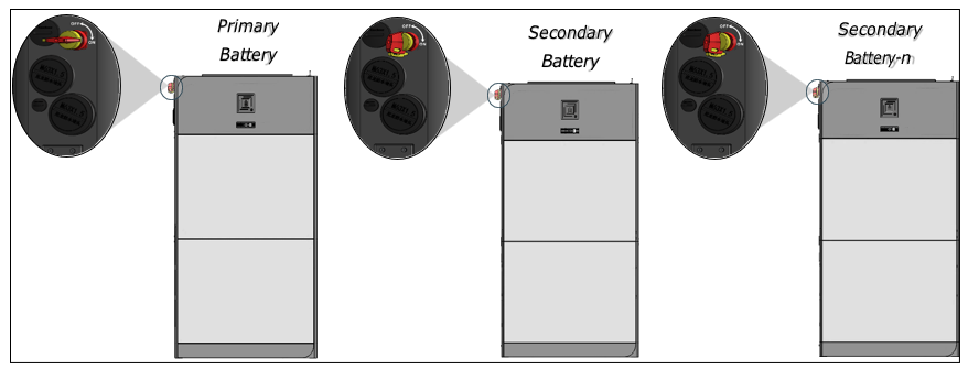
2. Turn ON the Disconnect on the eWay. For paralleled battery systems, only turn on the Primary Battery
1. Turn on the Inverter Battery Breaker on the Inverter
2. Turn ON the Disconnect on the eWay. For paralleled battery systems, only turn on the Primary Battery
Programming the Inverter
SCHNEIDER:
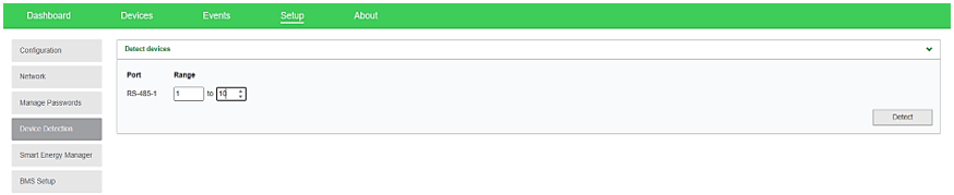
1. Connect to Schneider’s Insight Local2. Go to SETUP>CONFIGURATION>MODBUS SETTINGS and select 19200 Baud Rate. Click Apply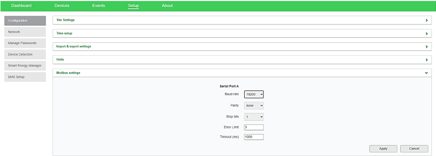 3. Go to SETUP>Device Detection> input range 1-10. Click Detect.
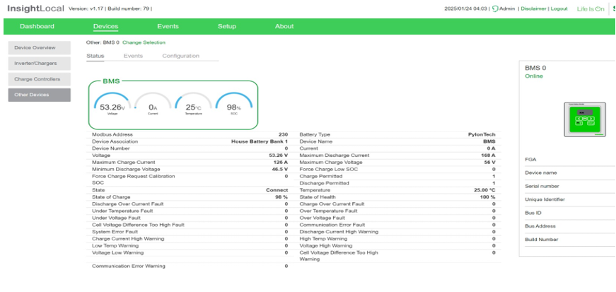
 4. Make sure that Insight Home is reading the battery internal parameters
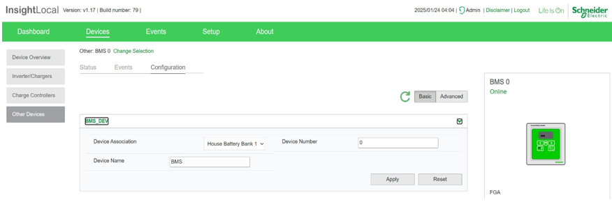
 5. Associate Battery as House Battery Bank 1
 Parameter Settings
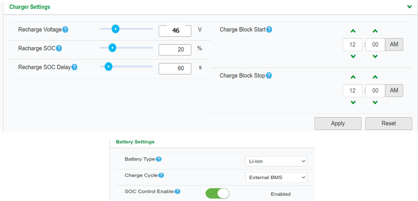
PARAMETER VALUECHARGER SETTINGS
RECHARGE VOLTAGE 46V RECHARGE SOC 20% RECHARGE SOC 60s
BATTERY SETTINGS
BATTERY TYPE LI-ION CHARGE CYCLE EXTERNAL BMS SOC CONTROL ENABLE ENABLED BATTERY BANK CAPACITY 200aH per eForce MAXIMUM CHARGE RATE 100% MAXIMUM BULK CHARGE CURRENT 120A per eForce MAXIMUM ABSORPTION CHARGE CURRENT 120A per eForce MAXIMUM FLOAR CHARGE 120A per eForce DEFAULT BATTERY TEMPERATURE WARM ABSORPTION TIME 3600 BULK/BOOST VOLTAGE 51.5 ABSORPTION VOLTAGE SET POINT 51.5 MAXIMUM DISCHARGE CURRENT 160A per eForce MAXIMUM DISCHARGE TIME INTERVAL 8 LOW BATTERY CUT OUT 44.8V LOW BATTERY CUT OUT DELAY 10s LOW BATTERY CUT OUT HYSTERESIS 2 LOW BATTERY CUTOUT WARNING OFFSET 2 HIGH BATTERY CUT OUT 58V CHARGE CYCLE TIMEOUT 1440s HIGH SOC CUT OUT 99% HIGH SOC CUT OUT DELAY 2s LOW SOC CUT OUT 15% LOW SOC CUT OUT DELAY 60s
1. Connect to Schneider’s Insight Local
2. Go to SETUP>CONFIGURATION>MODBUS SETTINGS and select 19200 Baud Rate. Click Apply
3. Go to SETUP>Device Detection> input range 1-10. Click Detect.
4. Make sure that Insight Home is reading the battery internal parameters
5. Associate Battery as House Battery Bank 1
Parameter Settings
PARAMETER VALUE
CHARGER SETTINGS |
RECHARGE VOLTAGE | 46V |
| RECHARGE SOC | 20% |
RECHARGE SOC | 60s |
BATTERY SETTINGS |
BATTERY TYPE | LI-ION |
CHARGE CYCLE | EXTERNAL BMS |
SOC CONTROL ENABLE | ENABLED |
BATTERY BANK CAPACITY | 200aH per eForce |
MAXIMUM CHARGE RATE | 100% |
MAXIMUM BULK CHARGE CURRENT | 120A per eForce |
MAXIMUM ABSORPTION CHARGE CURRENT | 120A per eForce |
MAXIMUM FLOAR CHARGE | 120A per eForce |
DEFAULT BATTERY TEMPERATURE | WARM |
ABSORPTION TIME | 3600 |
BULK/BOOST VOLTAGE | 51.5 |
ABSORPTION VOLTAGE SET POINT | 51.5 |
MAXIMUM DISCHARGE CURRENT | 160A per eForce |
MAXIMUM DISCHARGE TIME INTERVAL | 8 |
LOW BATTERY CUT OUT | 44.8V |
LOW BATTERY CUT OUT DELAY | 10s |
LOW BATTERY CUT OUT HYSTERESIS | 2 |
LOW BATTERY CUTOUT WARNING OFFSET | 2 |
HIGH BATTERY CUT OUT | 58V |
CHARGE CYCLE TIMEOUT | 1440s |
HIGH SOC CUT OUT | 99% |
HIGH SOC CUT OUT DELAY | 2s |
LOW SOC CUT OUT | 15% |
LOW SOC CUT OUT DELAY | 60s |
Related Articles
eForce Inverter Integration Guide (EcoVault)
Important Notice This Quick Guide does not exempt the installer or User from reading each product manual. Failure to do so may risk damaging both Fortress Power equipment and other manufacturers and void warranty. Connection Diagrams Connection ...eForce Inverter Integration Guide (Victron)
Important Notice This Quick Guide does not exempt the installer or User from reading each product manual. Failure to do so may risk damaging both Fortress Power equipment and other manufacturers and void warranty. Connection Diagrams Connection ...eForce Installation Manual
1. Abbreviations 2. Change Log VERSION CHANGE DESCRIPTION EM-V1.0 EM-V1.2 1. Include Pinout definition EM-V1.3 2. Vertical installation with inverter instructions added EM-V1.4 1. Added dimensions for 2-3 battery vertical installation. 2. Changed ...eForce Inverter Integration Guide (ENVY)
Important Notice This Quick Guide does not exempt the installer or User from reading each product manual. Failure to do so may risk damaging both Fortress Power equipment and other manufacturers and void warranty. Connection Diagrams Connection ...eForce Wall-Mount Installation Manual
Safety and Precaution Instructions Mounting a heavy lithium battery to a wall requires careful planning and adherence to safety standards to prevent injury, equipment damage, or property hazards. Below are detailed instructions considering best ...